Vacuum loader with filter doors

a vacuum cleaner and filter door technology, applied in the direction of dispersed particle separation, transportation and packaging, separation processes, etc., can solve the problems of affecting the efficiency and operability of equipment, affecting the health and safety of operating personnel and other on-site employees, and dust damage, etc., to improve material separation, dampen the noise emitted by the motor and the pump

Inactive Publication Date: 2006-09-21
DEMARCO VACUUM CORP
View PDF99 Cites 38 Cited by
  • Summary
  • Abstract
  • Description
  • Claims
  • Application Information

AI Technical Summary

Benefits of technology

[0014] The novel vacuum loader or industrial vacuum cleaner efficiently removes airborne as well as settled dust (particulates) comprising particulate matter, metal slivers, plastic chips, wood shaving, dirt, sand, debris and waste from industrial plants and other locations as well as has other uses. Advantageously, the outstanding vacuum loader or industrial dust collector with a side access door in the filtering compartment is reliable, safe and effective. Desirably, the user-friendly vacuum loader or industrial dust collector with a side access door in the filtering compartment can also be movable, portable, or towable, and can be used in a stationary manner. The special vacuum loader or industrial dust collector with side access door in the filtering compartment can accommodate standard and different size and types of bins and hoppers. Furthermore, the multiple use industrial loader dust collector with a side access door in the filtering compartment provides a superb industrial vacuum cleaner, vacuum loader, and vacuum conveyor.
[0015] The vacuum loader or industrial dust collector has a solids-gas separating (separation) compartment with a tangential cyclone separator, preferably a perforated tangential cyclone separator comprising a foraminous upright curved wall plate, ring or tube or louvers, to effectively remove large particulates of dust from a dusty gas stream. In the preferred form, the perforated tangential cyclone separator has angular perforations to increase kinetic separation and removal of particulates (dust). The perforations can comprise holes, slits, slots, cuts, or passageways that are drilled, punched, spaced or otherwise formed at an angle of inclination to the exterior surface(s) of the tangential cyclone separator to increase the kinetic energy of separation of particulate from dust-laden streams. The solids-gas separator can also have a perforated, foraminous or solid a barrier wall portion comprising an impact plate separator (strike plate). The tangential cyclone separator and the impact plate separator can comprise a deflector(s) which changes the direction of flow of the incoming dusty gas stream.
[0017] In one preferred form, the filter (filtering) compartment can be positioned generally along side and spaced laterally away from the solids-gas separating compartment and in offset relationship thereto, rather than vertical alignment or completely above the solids-gas separation compartment. The filtering compartment has at least one filter to filter a portion of the dusty gas stream. At least one compressed air tank communicating with the filtering compartment is provided. Also, at least one air injector is operatively connected to the compressed air tank to inject compressed air with sufficient kinetic energy into the filter in the filtering compartment to help clean the filter. An intermediate conduit can be provided to pass a portion of the dusty gas stream exiting the solids-gas separating compartment to the filtering compartment. A discharge conduit can be connected to the filtering compartment to discharge the filtered portion of the dusty gas stream from the filtering compartment.
[0018] The vacuum loader greatly improves the separation of material from an air stream in a material collection chamber via a primary tangential cyclone separator. The material and air are pulled by vacuum or pushed by pressure to the tangential cyclone separator for separation of the material from the air stream so that the material can drop into the container and the separated air can flow to the air outlet port.
[0019] In an illustrated form, a hopper comprising a bin is positioned below and supports the solids-gas separation compartment and the filter compartment(s). A vacuum pump can be connected to a motor to draw (suck) influent dusty air through the inlet conduit(s) into the solids-gas separating compartment. Preferably, a sound attenuating device comprising a muffler is provided to dampen noise emitted from the motor and pump.
[0021] Advantageously, the vacuum loader or industrial dust collector with a perforated tangential separator can achieve unexpected surprisingly good results with excellent efficiency in the separation of particulate matter from dusty air streams. This may be attributable to greater angular kinetic separation of the dusty particulates through the angular perforations and along the perimeter or circumference of the perforated tangential cyclone separator or other solids-gas separator. It is also believed that the angular perforations provide for more efficient gross cut separation of the larger particulates of dust by the perforated solids-gas separator. Furthermore, the vacuum loader or industrial dust collector with the perforated tangential cyclone separator provide for superb separation, dedusting, and purification of the dusty gas stream to provide for cleaner emissions and better compliance with environmental laws and regulations.

Problems solved by technology

Dust is carried and circulated in the air and can be injurious to the health and safety of operating personnel and other on site employees.
Dust can damage, erode, and adversely effect the efficiency and operability of equipment.
It can also create a fire hazard and cause explosions in some situations, such as in grain elevators.
Voluminous amounts of dust can pollute the atmosphere.
Dust may also impair the quality of the products manufactured.
Dust emissions are not only dangerous and troublesome, but are particularly aggravating and grievous where relatively dust-free conditions and sterile environments are required, such as in medical supply houses, the electronics industry, and in food-processing plants.
In the past, access to insert and remove these filters in vacuum loaders has been through a top or bottom opening in the filter compartment, which has been difficult, cumbersome, and awkward.

Method used


Image

  • Vacuum loader with filter doors
  • Vacuum loader with filter doors
  • Vacuum loader with filter doors

Examples


Embodiment Construction

[0036] A detailed description of the preferred embodiments and best modes for practicing the invention are discussed herein.

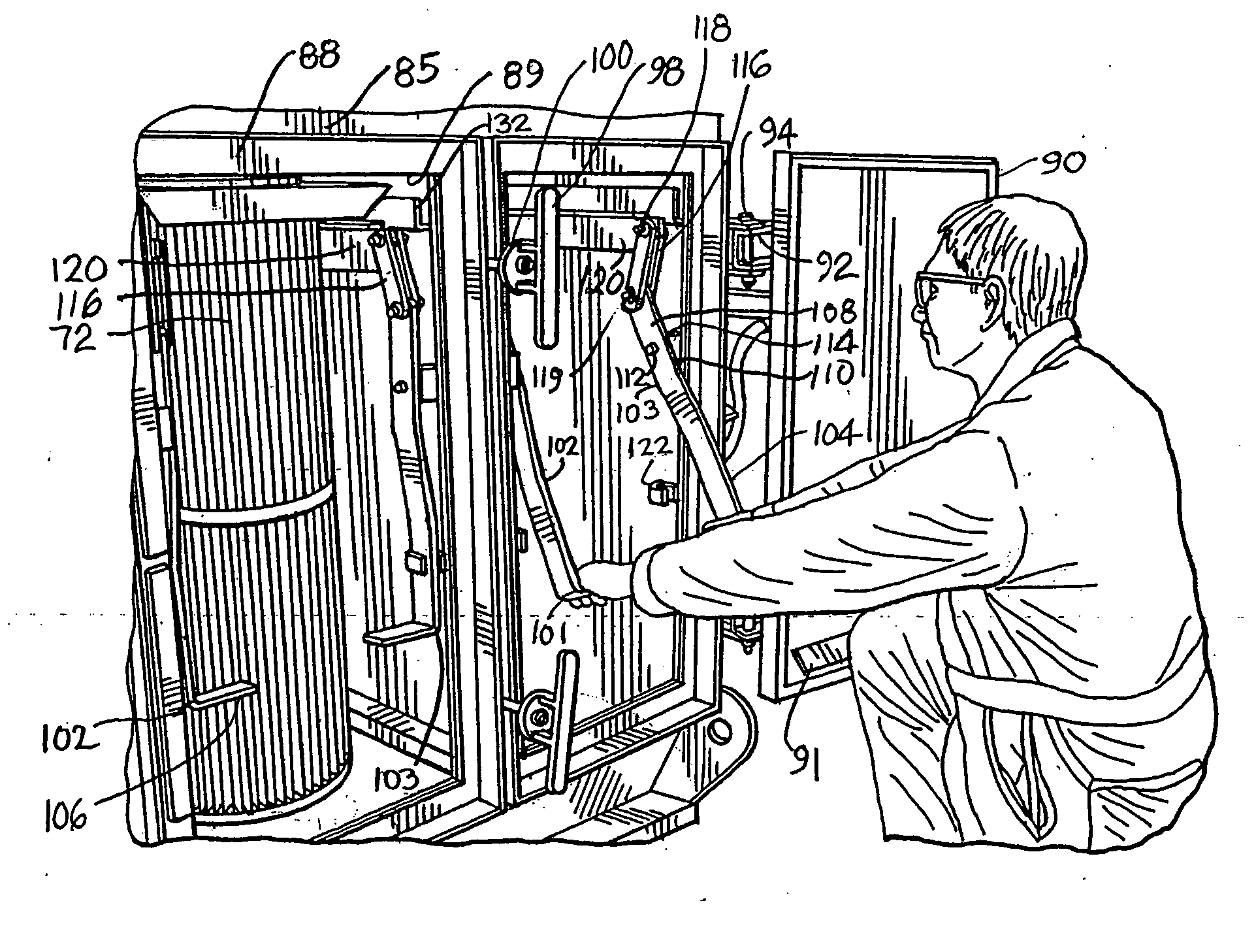
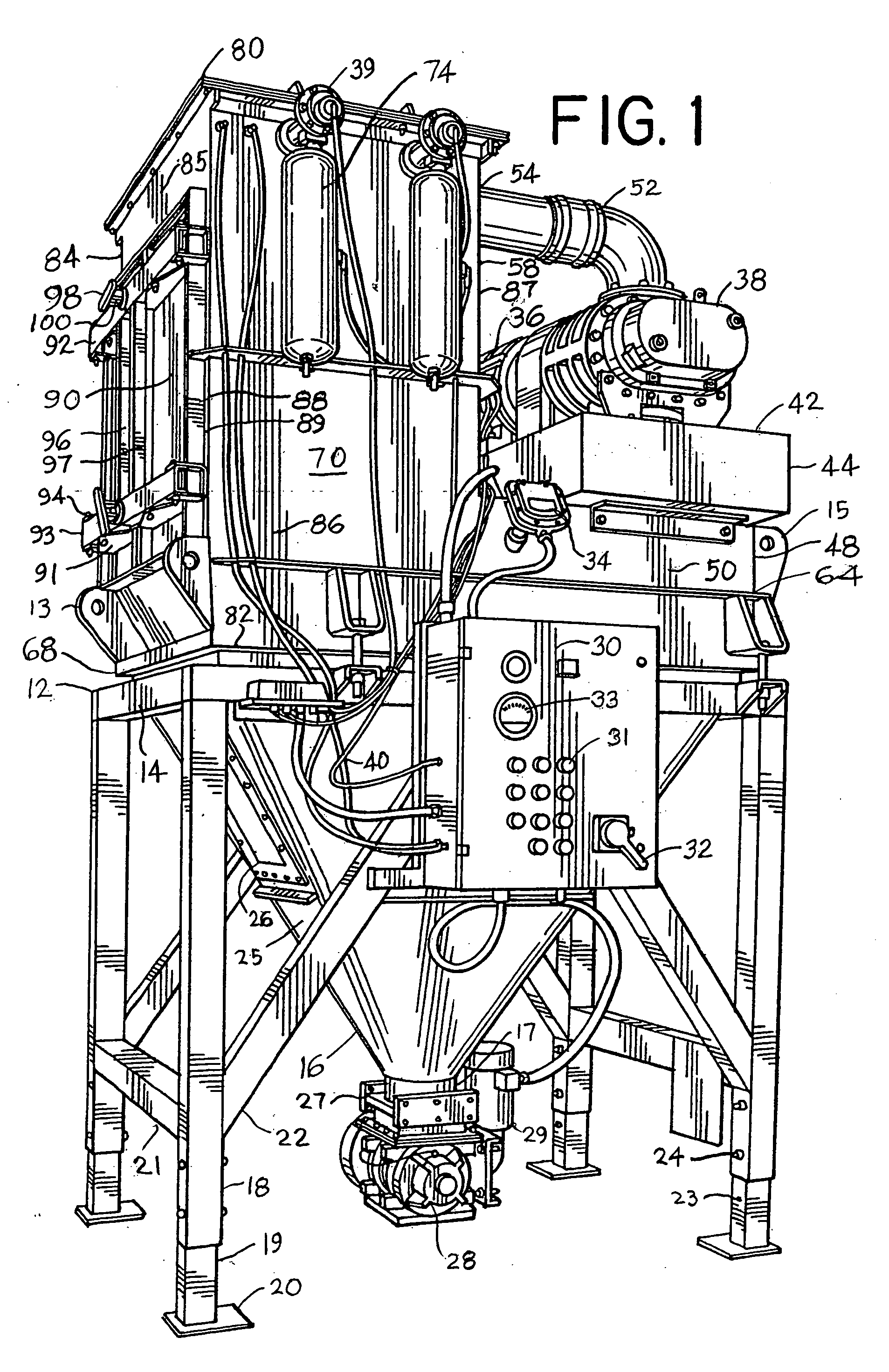
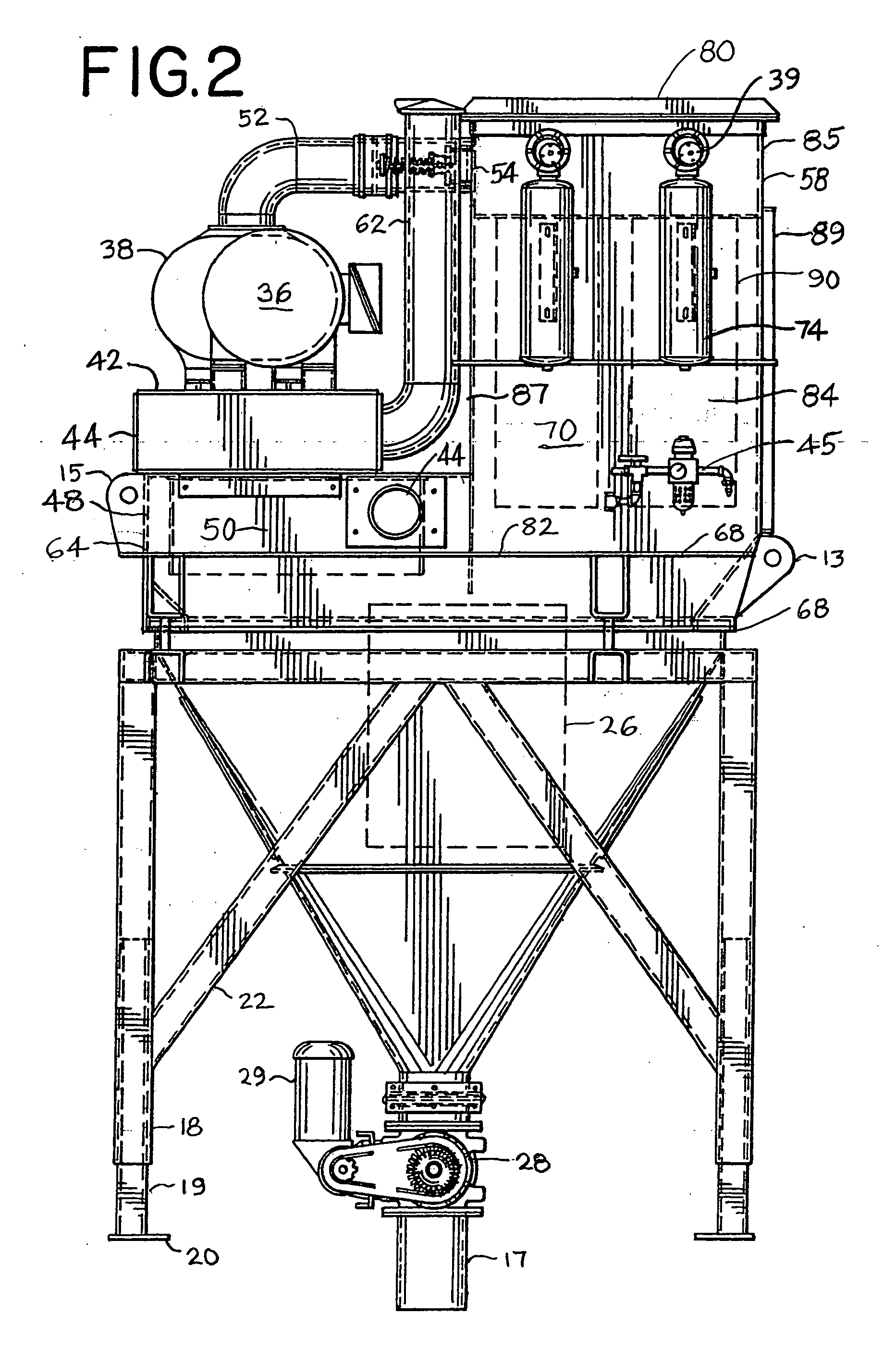
[0037] An industrial dust collector 10 (FIGS. 1-5) provides a heavy-duty vacuum-operated machine, industrial vacuum cleaner, vacuum loader and vacuum conveyor or pneumatic conveyor to efficiently remove, effectively collect, and safely dispose or convey (transfer) particulate matter, debris, and waste. The industrial dust collector can be made of steel or other metal. Other materials can be used. The vacuum loader or industrial dust collector 10 can have a frame assembly 12 with a base 14 which provides a support platform and a cradle for receiving a hopper 16 comprising a bin such as an end dump hopper. The bin (hopper) has at bottom end with a downwardly facing discharge pipe and conduit providing a hopper outlet 17. In the illustrative embodiment, the hopper comprising a bin is positioned below and supports the solids-gas separating (separation) compartment...


PUM

PropertyMeasurementUnit
angle of inclinationaaaaaaaaaa

Abstract

An improved industrial vacuum loader is equipped with a special filter door system to permit insertion, removal, inspection, and maintenance of filters during maintenance and to safely close and lock the filters during operation of the industrial vacuum loader. The industrial vacuum loader can have a solids-gas separation compartment with a tangential cyclone separator which is preferably positioned generally alongside and laterally offset from one or more filtering compartments to minimize turbulence and re-entrainment of the collected particulate material.

Description

CROSS REFERENCE TO RELATED APPLICATIONS [0001] This application is a continuation-in-part of U.S. patent application Ser. No. 10 / 389,792 filed Mar. 17, 2003, now U.S. Pat. No. 6,936,085 issued Aug. 30, 2005 entitled “Vacuum Loader” and U.S. patent application Ser. No. 11 / 162,024 filed Aug. 25, 2005 entitled “Vacuum Loader”.BACKGROUND OF THE INVENTION [0002] This invention pertains to machines for removing or transfer dry and wet liquid particulates, and more particularly, to an industrial vacuum cleaner, loader, pneumatic conveyor, or industrial dust collector. [0003] In industry, voluminous amounts of particulate matter, debris, and waste are emitted during machining, foundry, milling, shipment, warehousing, assembling, fabricating, and other manufacturing operations. Particulates of dust emitted during a manufacturing operation can include metal slivers, plastic chips, wood shavings, dirt, sand, and other debris. Dust accumulates on floors, machines, packaging materials, equipment...

Claims


Application Information

Patent Timeline
Patent Type & Authority Applications(United States)
IPC IPC(8): B01D50/00
CPCB01D45/08B01D45/12B01D46/0005B01D46/008B01D50/002B01D46/88B01D50/20
Inventor DEMARCO, THOMAS M.
Owner DEMARCO VACUUM CORP
Why Eureka
Try Eureka