Relay switch for toaster

a technology of relay switch and toaster, which is applied in the direction of contact mechanism, lighting and heating apparatus, etc., can solve the problems of devastating consequences, accidents and personal harm, and the automatic urging mechanism of the toasting tray might not be able to rebound in practice,

Inactive Publication Date: 2006-09-21
ZHANG GEORGE MOHAN +1
View PDF5 Cites 17 Cited by
  • Summary
  • Abstract
  • Description
  • Claims
  • Application Information

AI Technical Summary

Benefits of technology

[0008] A primary object of the present invention is to provide a toaster relay switch for solving the above mentioned drawbacks of conventional toaster, whe

Problems solved by technology

However, occasionally due to some accidental factors, the automatic urging mechanism of the toasting tray might fail to rebound in practice.
The consequences of such failure would be devastating.
This is due to the fact that the switch of the power source could not be severed off; the coils would be powered for an extended period of time thus singing the bread as well as resulting accidents and personal harms.
This overtime toasting would cause over-baked bread useless, even bring serio

Method used


Image

  • Relay switch for toaster
  • Relay switch for toaster
  • Relay switch for toaster

Examples


second embodiment

[0070] Referring to FIG. 9, the toaster under a power-on circumstance according to the present invention is illustrated. The hooking assembly comprises relay casing 5, a supporting stand 2 provided at the top portion of the relay casing 5, an inverted T shape latch having a horizontal end hinged onto the supporting stand 2, and another end integrally combined with an engaging metal holder 1′-3. A U shape positioning element 26 is provided for maneuvering the engagement between the electromagnet and the engaging metal. The U shaped positioning element 26 has a lower leg 26-2 hinged onto the base stand 11-2, and an upper leg positioned above the lower projector of the hook member, wherein the lower leg is positioned below the free end of the engaging metal 4. furthermore, the U shaped positioning element 26 is provided with a homing spring 27, which is mounted between the upper leg 26-1 and supporting lug 11-1.

[0071] Referring to FIG. 10, the toaster under a power-off condition accord...

fourth embodiment

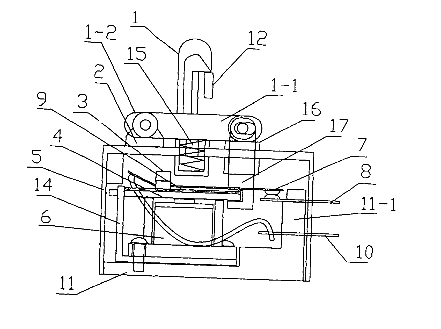
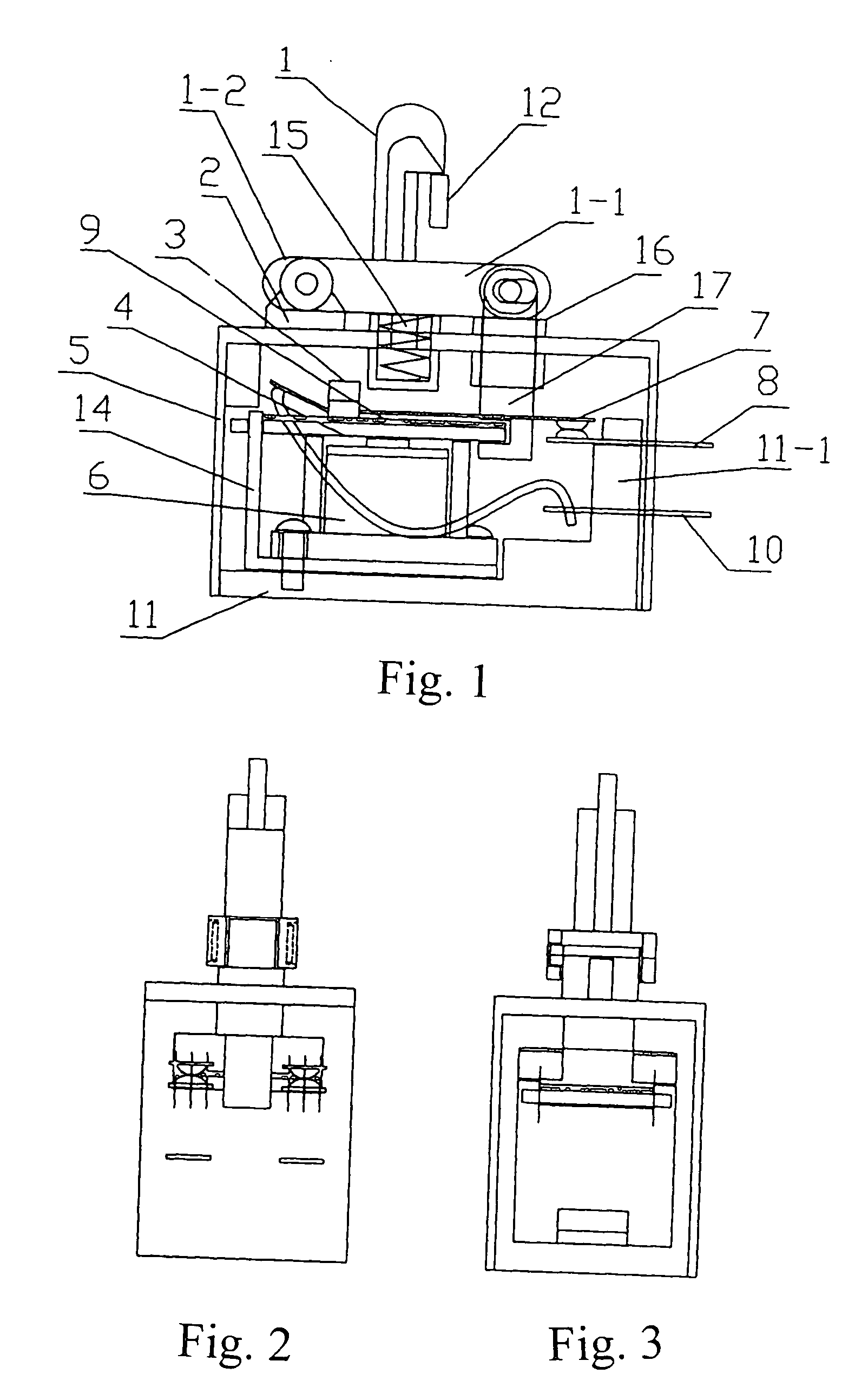
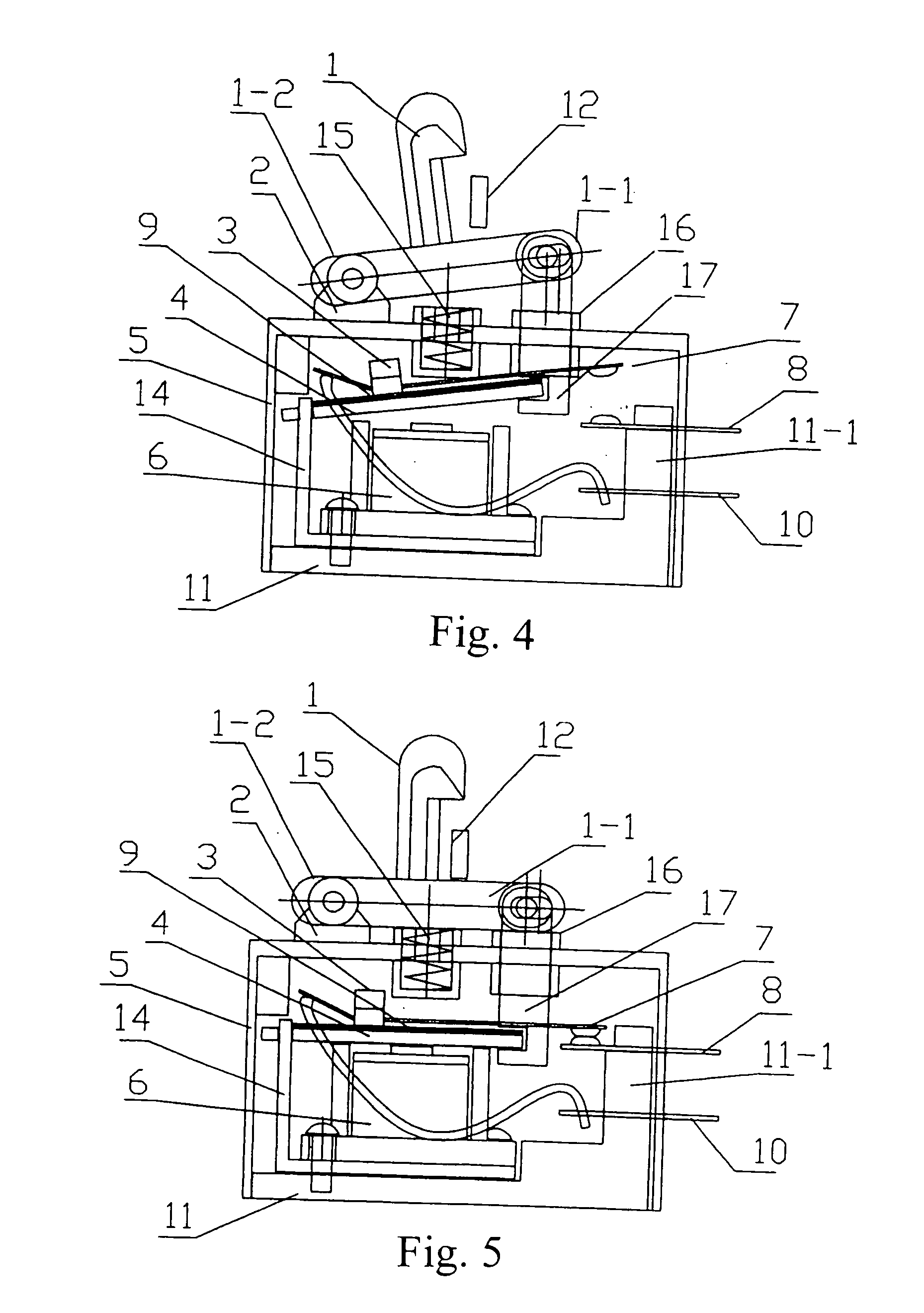
[0079]FIG. 22 illustrates the present invention, wherein the switch leaf 7 and the power slab 8 are inverted L shaped, wherein contacts are respectively provided onto vertical legs thereof at an aligned elevation. What is more, the pressing pin is sidewardly projected from the engaging metal holder 17 to releasably bias against the vertical leg of the switch leaf 7, such that the lowered pressing pin will depress the switch leaf rightward deformed thus forcing contacts respectively positioned onto the lower legs of the switch leaf 7 and the power slab engaged. It is noted that the electrical tabs of the switch leaf 7 and the power slab 8 are mounted onto right wall of the switch casing 5 with a spaced parallel status.

fifth embodiment

[0080]FIG. 23 and FIG. 24 illustrate the present invention, wherein the switch leaf 7 is L shape defined, and the power slab 8 is straight single line shaped. One end of the L shaped switch leaf 7 is mounted onto the right wall of the switch casing 5, while the other end of the L shaped switch leaf 7 is positioned above the power slab 8 for aligning the contacts respectively defined onto the switch leaf 7 and the power slab 8. It is noted that the pressing pin is defined as a furcated metal element having two ends alternative inserted into the switch leaf 7 and the power slab 8, such that the lowered engaging metal holder 17 will enable two ends of the furcated metal simultaneously engage with the switch leaf 7 and the power slab 8 for completing the circuit.


PUM


Abstract

The present invention discloses a relay switch arrangement for a toaster, the arrangement has an actuating member releasably engaged to the engaging metal positioned above the electromagnet, and shifted between a power-on position and a power-off default position. A homing spring is provided biasing against the actuating member for maintaining the actuating member in the power-off position. Electrical contacts are respectively provided onto a pair of power slabs for selectively completing the circuit, wherein in the power-on position, the actuating member drives two contacts approach with each other complete the circuit to charge the electromagnet attracting the engaging metal, in the power-off default position, the circuit is powered off enabling the electromagnet to release the engaging metal, the homing spring will upwardly push the actuating member thus driving the engaging metal tilt up so as to disengage the pair of contacts for security purposes.

Description

BACKGROUND OF THE PRESENT INVENTION [0001] 1. Field of Invention [0002] The present invention relates to electrical heating devices, and more particularly, relates to a kind of relay switch used for toaster. [0003] 2. Description of Related Arts [0004] For lots of people, the toaster is a daily part of breakfast. Commonly, an electrical toaster comprises an outer casing, a handle, a base, an electrical timer, and a PCB module. The basic idea behind the toaster is simple. A toaster uses infrared radiation to heat a piece of bread. When a user put a piece of bread in and sees the coils glow red, the coils would produce infrared radiation to dry and char the surface of the bread. The timer is adapted to set a toasting time, turn the toaster off automatically after the preset time runs up and at the same time releases the tray so that toasted bread pops up. Accordingly, a user is able to freely and selectively set the toasting time according to his preference of toast darkness. [0005] O...

Claims


Application Information

Patent Timeline
IPC IPC(8): A47J37/08
CPCA47J37/0842H01H3/503H01H2009/305A47J37/08H01H3/32H01H50/16
Inventor ZHANG, GEORGE MOHANCHEN, HUAJIN
Owner ZHANG GEORGE MOHAN
Why Eureka
Try Eureka