Method for manufacturing color filters

a color filter and manufacturing method technology, applied in the direction of liquid surface applicators, coatings, instruments, etc., can solve the problems of mainly determined relatively time-consuming and complicated lithography process, and the cost of the color filter is about 28% of the total cost of the liquid crystal display device, so as to enhance the manufacturing efficiency, reduce the manufacturing cost thereof, and enhance the manufacturing efficiency

Inactive Publication Date: 2006-09-21
HON HAI PRECISION IND CO LTD
View PDF12 Cites 5 Cited by
  • Summary
  • Abstract
  • Description
  • Claims
  • Application Information

AI Technical Summary

Benefits of technology

[0013] The means of imprinting can form the black matrix layer quickly. This enhances a manufacturing efficiency and decreases a manufacturing cost thereof. Furthermore, the multi-head ink-jet array can color the black matrix layer by jetting ink once. This enhances a manufacturing efficiency, saves the ink and decreases a manufacturing cost. Therefore, the method has an enhanced efficiency and a decreased cost.

Problems solved by technology

The cost of the color filter is about 28% of a total cost of the liquid crystal display device.
That is, the cost of the liquid crystal display device is mainly determined by the manufacturing cost of the color filter.
The lithography process is relatively time-consuming and complicated.
Thus, the manufacturing cost of the black matrix by the conventional methods is relatively high.
However, the dyes have poor light resistance and heat resistance.
Furthermore, a cost of the dyes and the manufacturing devices is relatively high, and a manufacturing process is relatively time-consuming.
Thus, the dyeing method has a relatively high cost and is unsatisfactory.
However, a smoothness and uniformity of the pigments on the black matrix layer can't be readily controlled.
Furthermore, the cost of the manufacturing devices is relatively high and the manufacturing process is relatively long.
Thus, the pigment dispersed method has a relatively high cost and is unsatisfactory.
However, a smoothness and uniformity of the inks on the black matrix layer can't be readily controlled.
Furthermore, the manufacturing process is relatively time-consuming.
Thus, the printing method is unsatisfactory.
However, the cost of the manufacturing devices is relatively high.
Furthermore, a manufacturing process is relatively time-consuming and complicated.
Thus, the electrodeposition method has a relatively high cost and is unsatisfactory.

Method used


Image

  • Method for manufacturing color filters
  • Method for manufacturing color filters
  • Method for manufacturing color filters

Examples


Embodiment Construction

[0024] Reference will now be made to the drawings to describe embodiments of the present method.

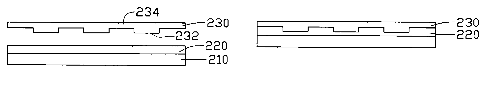
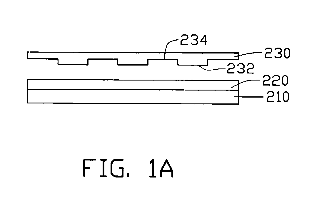
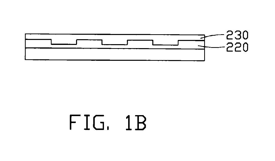
[0025] Referring to FIG. 7, the present method for manufacturing a color filter 200 comprises the steps of: (a) forming a black matrix layer 240 on a substrate 210 by means of imprinting; (b) coloring the black matrix layer 240 to form a color layer 250 thereon; and (c) forming an indium-tin oxide (ITO) layer 260 on the color layer 250.

[0026] The step (a) can be performed by means of nano-imprinting or hot embossing. Referring to FIGS. 1a-1d, the step (a) includes the steps of: (a1) disposing a photoresist film 220 on the substrate 210; (a2) using an imprinting stamper 230 having certain patterns (i.e., protrusions 232 and recesses 234) associated therewith to imprint the photoresist film 220, thereby the photoresist film 220 having certain patterns (i.e., recesses 2202 and protrusions 2204) directly associated with the certain patterns of the imprinting stamper 230; and (a3) removing t...


PUM


Abstract

A method for manufacturing a color filter includes the following steps: (a) forming a black matrix layer (240) on a substrate (210) by means of imprinting; (b) using a multi-head ink-jet array (MHIJA) (300) to color the black matrix layer, thereby forming a color layer (250) thereon; and (c) forming an indium-tin oxide (ITO) layer (260) on the color layer. The means of imprinting can form the black matrix layer quickly. This enhances a manufacturing efficiency and decreases a manufacturing cost. Furthermore, the multi-head ink-jet array can color the black matrix layer by jetting inks once. This enhances a manufacturing efficiency, saves the ink and decreases a manufacturing cost. Therefore, the method has an enhanced efficiency and a decreased cost.

Description

DESCRIPTION [0001] 1. Field of the Invention [0002] The invention relates generally to methods for manufacturing color filters; and more particularly, to a method for manufacturing a color filter, the method having an enhanced efficiency and a reduced cost. [0003] 2. Description of Related Art [0004] Color filters are generally used in liquid crystal display devices for converting white light beams transmitted therethrough into red light beams, green light beams and blue light beams. The red light beams, green light beams and blue light beams are configured for the liquid crystal display devices displaying color images. [0005] A typical color filter generally includes a substrate, a black matrix layer, a color layer, and an indium-tin oxide (ITO) layer. The black matrix layer is formed on the substrate and is used to separate sub-pixels of the color layer from each other. The color layer is formed on the black matrix layer and includes the red, green and blue sub-pixels. The indium-...

Claims


Application Information

Patent Timeline
Patent Type & Authority Applications(United States)
IPC IPC(8): G02B5/20
CPCG02B5/223G02F1/133512G02F1/133516
Inventor CHEN, GA-LANE
Owner HON HAI PRECISION IND CO LTD
Why Eureka
Try Eureka