Catalyst, electrode, membrane electrode assembly and fuel cell
a technology of membrane electrodes and catalysts, applied in the direction of cell components, physical/chemical process catalysts, metal/metal-oxide/metal-hydroxide catalysts, etc., can solve the problems of lowering the power generation efficiency of fuel cells and the inability of fuel cells to exhibit excellent power generation efficiency, and achieve excellent power generation efficiency
- Summary
- Abstract
- Description
- Claims
- Application Information
AI Technical Summary
Benefits of technology
Problems solved by technology
Method used
Image
Examples
example 1
[0114]
[0115] In the first step, a perovskite type oxide of Sr0.9Nd0.1TiO3, which is used as the catalyst carrier, was prepared as follows.
[0116] Specifically, mixed were SrCO3 (compound A shown in Table 1), which was manufactured by Rare Metallic Inc., and TiO2, which was manufactured by High Purity Chemical Inc., in a stoichiometric ratio, followed by provisionally burning the mixture at 1,100° C. for 10 hours under the air atmosphere. Then, the mixture was mixed again, followed by formally burning the mixture for 10 hours so as to obtain SrTiO3. Further, SrTiO3 was mixed with Nd2O3 (compound B shown in Table 1), which was manufactured by High Purity Chemical Inc., TiO2 and Ti, which was manufactured by High Purity Chemical Inc., in a stoichiometric ratio, followed by provisionally burning the mixture at 1,500° C. for 8 hours while allowing 5% H2 / Ar gas to flow into the burning system. Further, the mixture was mixed again, followed by formally burning the mixture at 1,600° C. for ...
examples 2 to 10
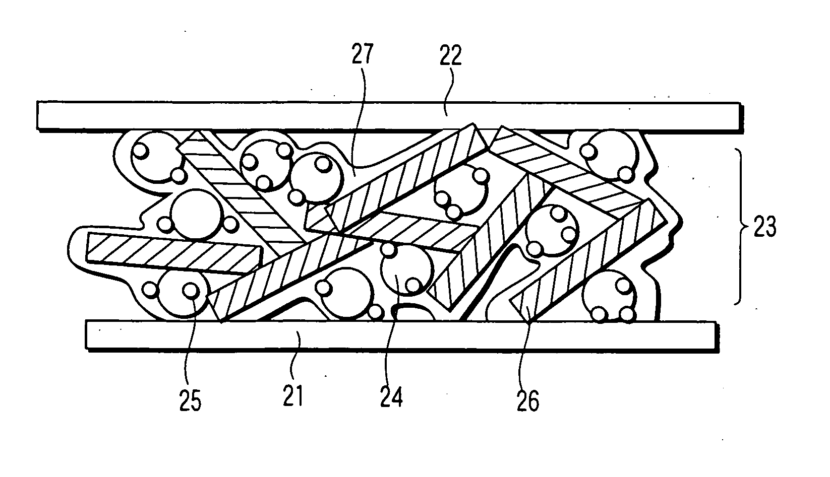
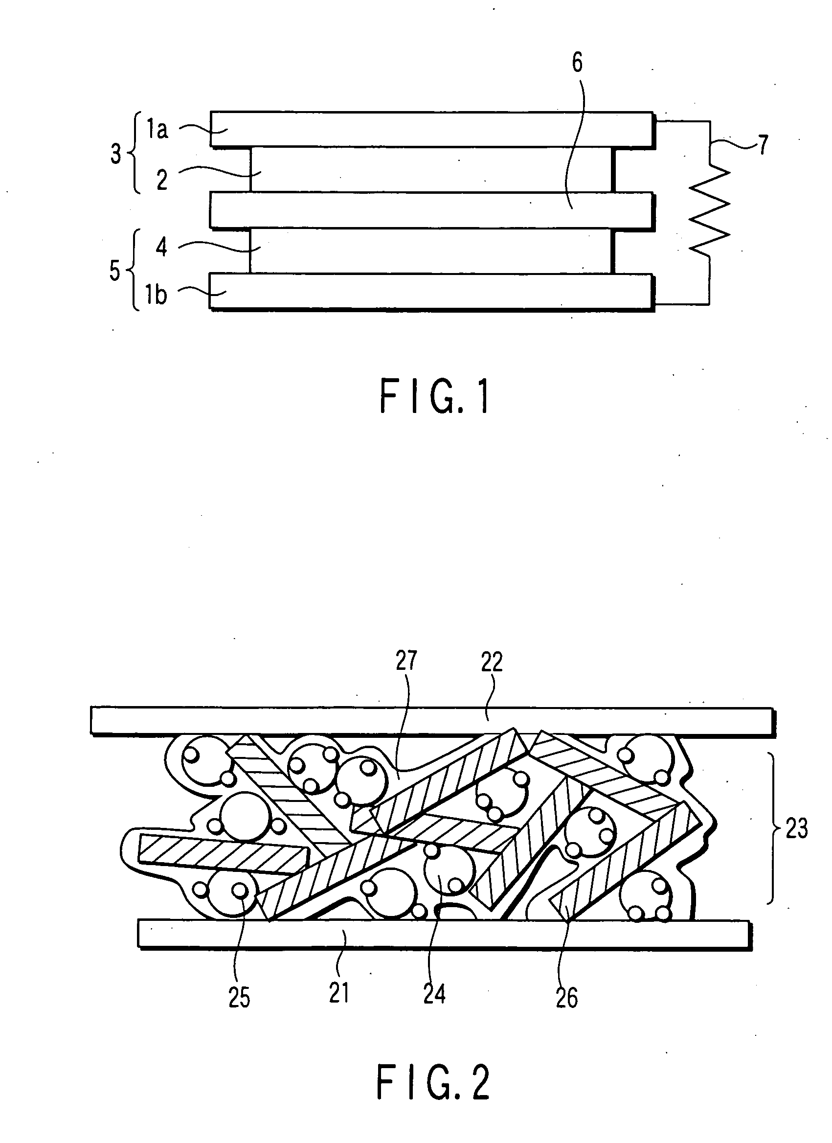
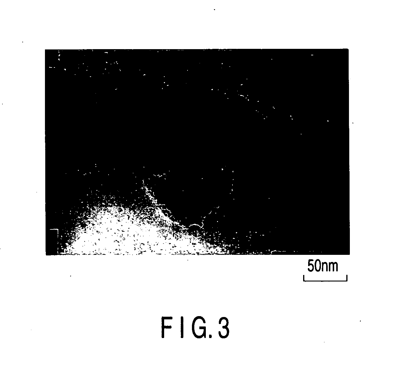
[0140] Various kinds of catalyst carriers as shown in Table 1 were obtained as in Example 1, except that the kinds of the compounds B were changed as shown in Table 1 and the mixing ratios of the compounds B were changed. Then, catalysts for the electrodes included in the fuel cells were manufactured as in Example 1, except that used were the catalyst carriers noted above. The surface of the catalyst thus manufactured was observed with a TEM, with the result that the gold particles (catalyst particles) were found to have been carried on the surface of the catalyst carrier. The average particle diameter of the catalyst particles was found to be 2 nm, and the average particle diameter of the catalyst carriers was found to be 100 nm. The CV measurement was applied to the catalysts thus manufactured as in Example 1. Table 1 also shows the results as in Example 1.
[0141] Then, cathodes were manufactured as in Example 1, except that used were the catalysts described above. Then, a fuel ce...
example 11
[0142] SrTiO3 obtained as in Example 1, La2O3 used as compound B, TiO2 and Ti were mixed in a stoichiometric ratio and, then, the mixture was sintered with SPS at 1170° C. so as to obtain the catalyst carrier of the kind shown in Table 1. Then, catalysts for the electrodes included in the fuel cells were manufactured as in Example 1, except that used were the catalyst carriers noted above. The surface of the catalyst thus manufactured was observed with a TEM, with the result that the gold particles (catalyst particles) were found to have been carried on the surface of the catalyst carrier. The average particle diameter of the catalyst particles was found to be 2 nm, and the average particle diameter of the catalyst carriers was found to be 100 nm. The CV measurement was applied to the catalysts thus manufactured as in Example 1. Table 1 also shows the results as in Example 1.
[0143] Then, cathodes were manufactured as in Example 1, except that used were the catalysts described above...
PUM
| Property | Measurement | Unit |
|---|---|---|
| Particle diameter | aaaaa | aaaaa |
| Particle diameter | aaaaa | aaaaa |
| Particle diameter | aaaaa | aaaaa |
Abstract
Description
Claims
Application Information
 - R&D
- Intellectual Property
- Life Sciences
- Materials
- Tech Scout
- Unparalleled Data Quality
- Higher Quality Content
- 60% Fewer Hallucinations
Browse by: Latest US Patents, China's latest patents, Technical Efficacy Thesaurus, Application Domain, Technology Topic, Popular Technical Reports.
© 2025 PatSnap. All rights reserved.Legal|Privacy policy|Modern Slavery Act Transparency Statement|Sitemap|About US| Contact US: help@patsnap.com


