Low cost flight instrumentation system
- Summary
- Abstract
- Description
- Claims
- Application Information
AI Technical Summary
Benefits of technology
Problems solved by technology
Method used
Image
Examples
Embodiment Construction
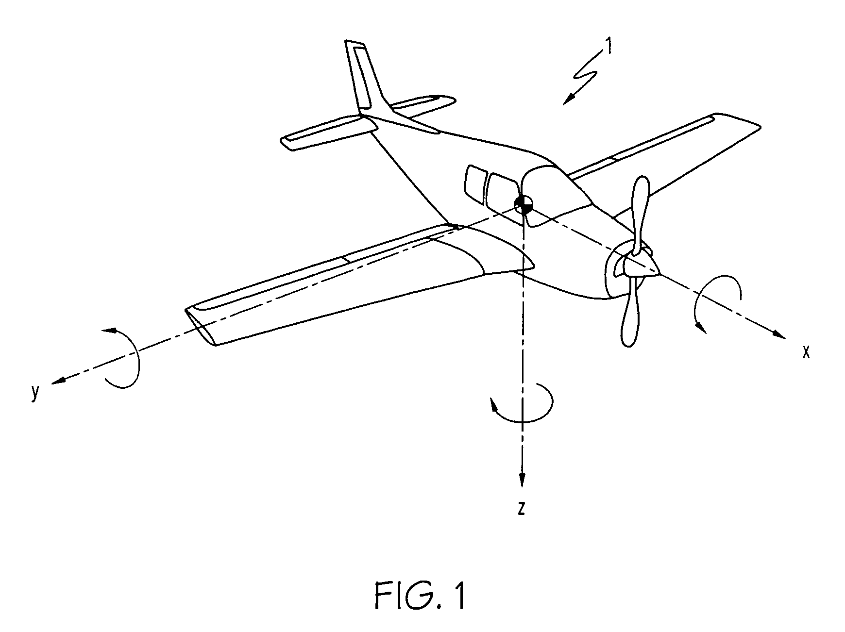
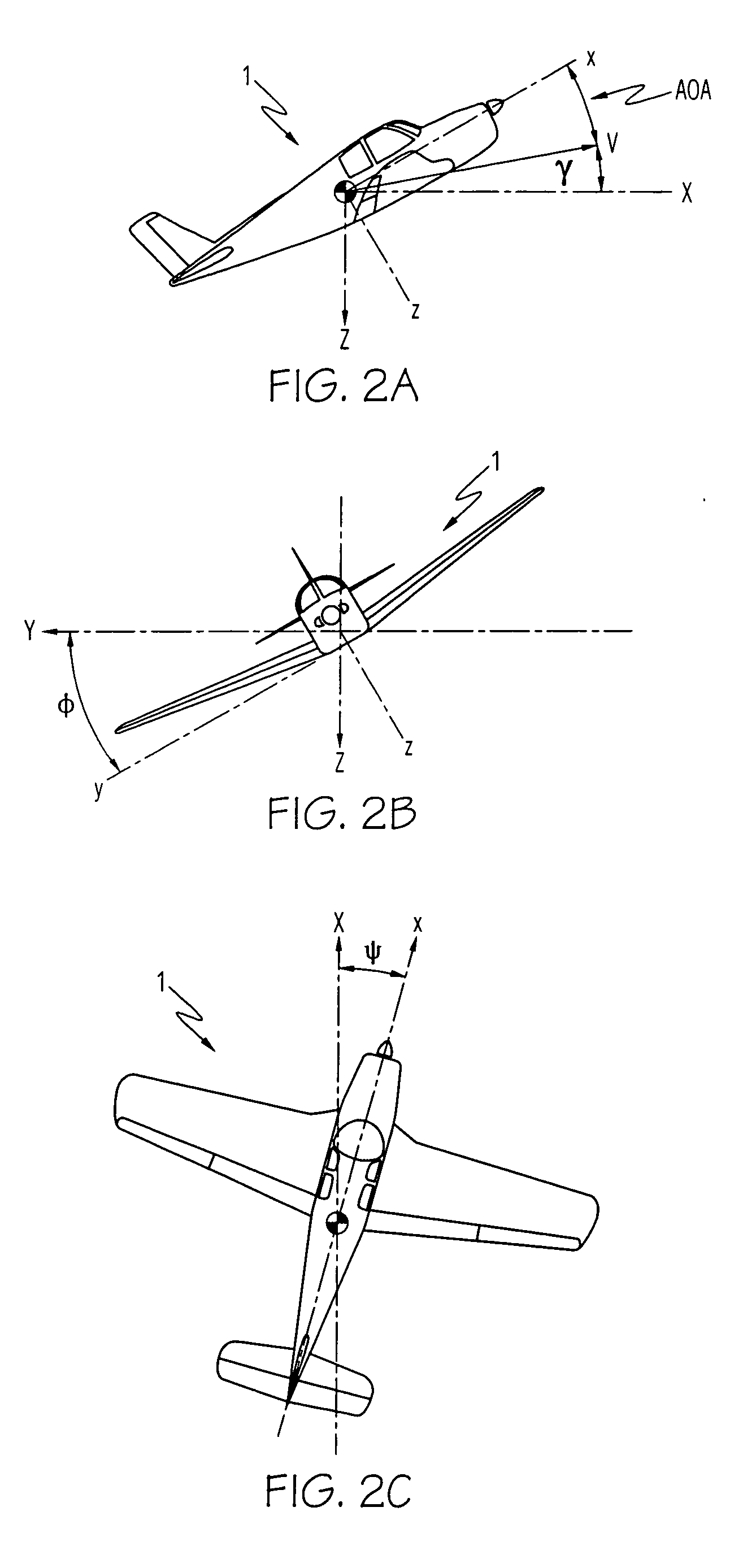
[0027] Referring initially to FIG. 1 and FIGS. 2A through 2C, a general aviation aircraft 1 is aligned along its three principal orthogonal aircraft body axes x, y and z is shown, where the three axes generally coincide with a Cartesian coordinate system with its vertex at the aircraft's center of gravity (CG). Referring with particularity to FIG. 2A through 2C, the aircraft's pitch, roll and yaw deviations from earth-referenced inertial axes are shown. In FIG. 2A, flight path angle is designated by angle γ (gamma), which is defined as the direction of travel (shown as velocity vector V) of aircraft 1 relative to the X (i.e., horizontal) inertial axis. Because of variations in aircraft weight, maneuver, and configuration, the pitch angle of aircraft 1 (the vertical angle between the x and X axes) can be significantly different than its flight path angle γ. AOA is defined as the angle between the velocity vector and the aircraft's longitudinal axis x, projected onto the aircraft's x-...
PUM
 Abstract
Description
Claims
Application Information
 - R&D
- Intellectual Property
- Life Sciences
- Materials
- Tech Scout
- Unparalleled Data Quality
- Higher Quality Content
- 60% Fewer Hallucinations
Browse by: Latest US Patents, China's latest patents, Technical Efficacy Thesaurus, Application Domain, Technology Topic, Popular Technical Reports.
© 2025 PatSnap. All rights reserved.Legal|Privacy policy|Modern Slavery Act Transparency Statement|Sitemap|About US| Contact US: help@patsnap.com


