Hybrid drive system of vehicle

a hybrid drive and drive system technology, applied in the direction of jet propulsion mounting, propulsion by capacitors, road transportation, etc., can solve the problems of inhibiting achieve the improvement of engine fuel economy, reduce drive loss, and facilitate connection

Active Publication Date: 2006-09-28
VOLVO LASTVAGNAR AB
View PDF4 Cites 14 Cited by
  • Summary
  • Abstract
  • Description
  • Claims
  • Application Information

AI Technical Summary

Benefits of technology

[0007] Therefore, according to the present invention, when the rotating electric machine is not operated, the rotating electric machine is separated from the drive system by the second clutch, and thus, it is possible that a load of the drive system generated by the inertial mass and friction of the rotating electric machine is reduced and the drive loss is decreased, leading to an improvement of the fuel economy of the engine.
[0008] Furthermore, the second clutch is connected after the difference between the input rotational speed and the output rotational speed is eliminated by the control of the rotational speed of the rotating electric machine, and therefore, the connection can be performed smoothly.

Problems solved by technology

In the system according to the Japanese Patent Laid-Open Publication No. 2000-343965, when the vehicle travels by only the engine output, the operation of the rotating electric machine is maintained in a stopped state, but the rotating electric machine remains to be connected to the drive system, and thus, the inertial mass and friction of the rotating electric machine cause a drive loss, which consequently inhibits the improvement of fuel economy of the engine.

Method used


Image

  • Hybrid drive system of vehicle
  • Hybrid drive system of vehicle
  • Hybrid drive system of vehicle

Examples


Embodiment Construction

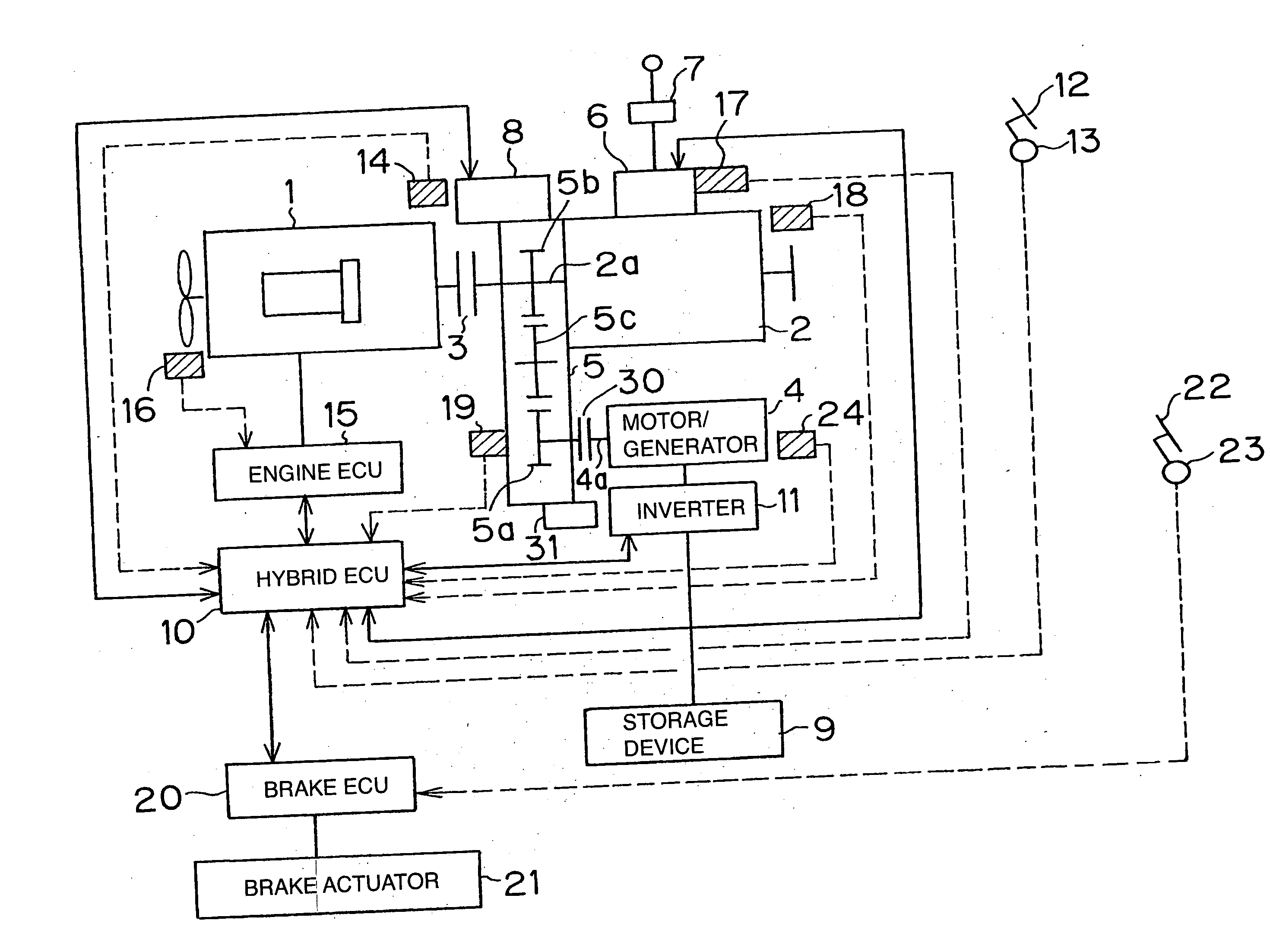
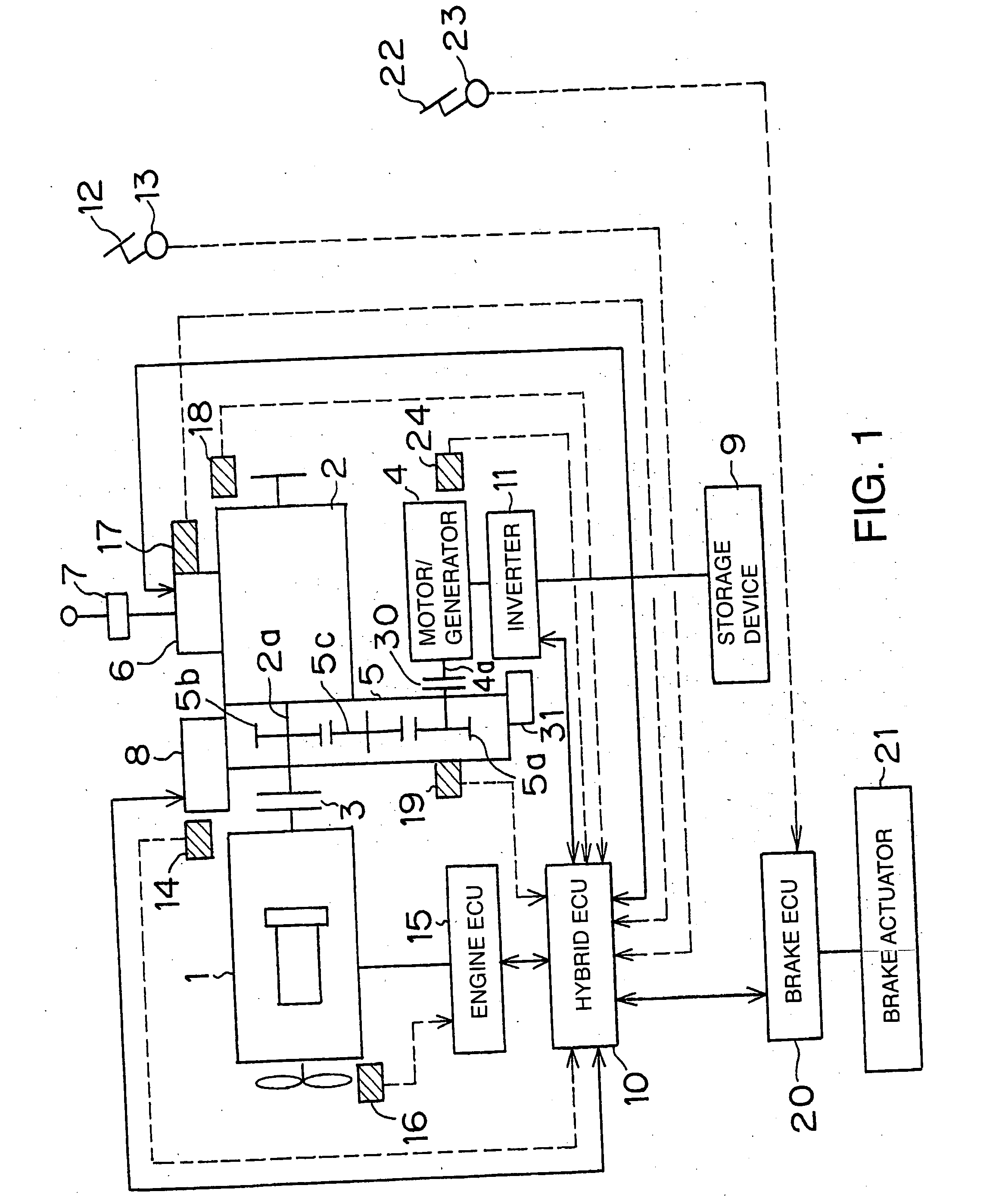
[0017] Referring to FIG. 1, the reference numeral 1 denotes an internal combustion engine and-the reference numeral 2 denotes a gear-type transmission, and a friction clutch 3 (first clutch) is interposed between them.

[0018] As the engine 1, a diesel engine or a CNG engine (engine which uses a Compressed Natural Gas as fuel) is used. The reference numeral 4 denotes a rotating electric machine (motor / generator), which serves as an electric generator and an electric motor. An input / output shaft 4a of the rotating electric machine 4 is coupled to a side of an input shaft 2a of the transmission 2 via a rotation transmission mechanism 5 as a gearbox.

[0019] The transmission 2 is provided with a control unit 6 to control a gearshift thereof. The control unit 6 is connected to a change lever unit 7 and a hybrid Electronic Control Unit 10 (hybrid ECU). When the change lever unit 7 generates a gearshift command, the control unit 6 controls the transmission 2 according to a signal from the h...


PUM


Abstract

A hybrid electric drive system for a vehicle comprises a combustion engine (1), a transmission (2), a first clutch (3) disposed between the engine (1) and the transmission (2), a rotating electric machine (4) which serves as a motor as well as a generator, a second clutch (30) disposed between the rotating electric machine (4) and the transmission (2), and a storage device (9). When the second clutch (30) is commanded to connect the rotating electric machine (4) to the transmission (2), a control unit (10) controls the rotating electric machine (4) so as to decrease the difference between the rotation speeds of the rotating electric machine (4) and the transmission (2) (S2) and cause the second clutch (30) to connect the rotating electric machine (4) to the transmission (2) only after the difference decreases to a allowable value (S3, S4).

Description

TECHNICAL FIELD [0001] The present invention relates to a hybrid drive system which is provided with an engine and a rotating electric machine (motor generator) as power sources of a vehicle. BACKGROUND OF THE ART [0002] As a hybrid drive system, Japanese Patent Laid-Open Publication No. 2000-343965 discloses a hybrid drive system which is provided with a path to transmit an engine output via a transmission to wheels and a path to input a rotating electric machine output to the transmission. [0003] Also, Japanese Patent Laid-Open Publication No. 2001-173479 discloses a hybrid drive system which is provided with a drive motor to drive a vehicle and an engine to drive an electric generator, and compensates for torque variation with the drive motor when the engine is started by the electric generator. [0004] In the system according to the Japanese Patent Laid-Open Publication No. 2000-343965, when the vehicle travels by only the engine output, the operation of the rotating electric mac...

Claims


Application Information

Patent Timeline
Patent Type & Authority Applications(United States)
IPC IPC(8): B60K1/00B60K6/387B60K6/48B60K6/54B60L50/16B60W10/02
CPCB60K6/387Y02T10/70B60L11/005B60L11/14B60L2240/421B60L2240/441B60W10/02B60W2510/0638B60W2510/081B60W2710/081Y02T10/6221Y02T10/7022Y02T10/7077Y02T10/76Y10S903/909Y10S903/914Y02T10/642B60K6/48B60L50/16B60L50/40Y02T10/62Y02T10/64Y02T10/7072
Inventor GOUDA, HIDEAKINISHINA, MITSUHIROSUZUKI, YUJI
Owner VOLVO LASTVAGNAR AB
Why Eureka
Try Eureka