Refraction measuring instrument

a technology of measuring instruments and refraction, which is applied in the field of refraction measuring instruments, can solve the problems of difficult to accurately measure the refraction of an eye to be examined in actual life, large burden on eyes, and physical and mental burdens on subjects, so as to reduce the size and weight of the instrument, improve the comfort of wearing, and reduce the burden on subjects. physical and mental burdens

Inactive Publication Date: 2006-09-28
KK TOPCON
View PDF2 Cites 180 Cited by
  • Summary
  • Abstract
  • Description
  • Claims
  • Application Information

AI Technical Summary

Benefits of technology

[0016] In order to achieve the above-mentioned objects, according to the fifth feature of the invention, there is provided the refraction measuring instrument according to any one of the first to fourth features of the invention in which the measuring means further includes separating means for separating an optical axis of the measurement light beam from the light source from an optical axis of the reflection light of the measurement light beam which is reflected on the eye to be examined. According to the invention, further reductions in size and weight of the instrument can be achieved. In particular, in the invention described in the third feature of the invention, improved wearing comfort can be provided and physical and mental burdens on the subject can be reduced.
[0017] In order to achieve the above-mentioned objects, according to the sixth feature of the invention, there is provided the refraction measuring instrument according to any one of the first to fifth features of the invention in which the measuring means includes: mark projecting means for projecting the measurement light beam from the light source as a mark of a predetermined pattern to the eye to be examined; imaging means for imaging the mark projected as the predetermined pattern by the mark projecting means; and calculating means for calculating the refraction of the eye to be examined based on a shape of the mark imaged by the imaging means. According to the invention, it is possible to provide a specific structure for performing objective refraction measurement on the eye to be examined using the measuring means.
[0018] In order to achieve the above-mentioned objects, according to the seventh feature of the invention, there is provided the refraction measuring instrument according to any one of the first to sixth features of the invention which further includes: eye movement measuring the means for measuring eye movement of the eye to be examined; driving means for driving the measuring means; and control means for controlling the driving means to cause the measuring means to follow the eye to be examined based on a result of the eye movement measured by the eye movement measuring means. According to the invention, even when the eye to be examined looks in each direction by the eye movement, accurate measurement can be performed while following the eye to

Problems solved by technology

Therefore, physical and mental burdens are placed on the subject.
In addition, it is difficult to accurately measure the refraction of an eye to be examined in actual life.
According to such a visual effect, sort of impractical operation may be forced to the eyes, so that the burden on the eyes becomes very large.
Secondly, the image display device is used in actual life, so it is nec

Method used


Image

  • Refraction measuring instrument
  • Refraction measuring instrument
  • Refraction measuring instrument

Examples


first embodiment

(Structure of Refraction Measuring Instrument)

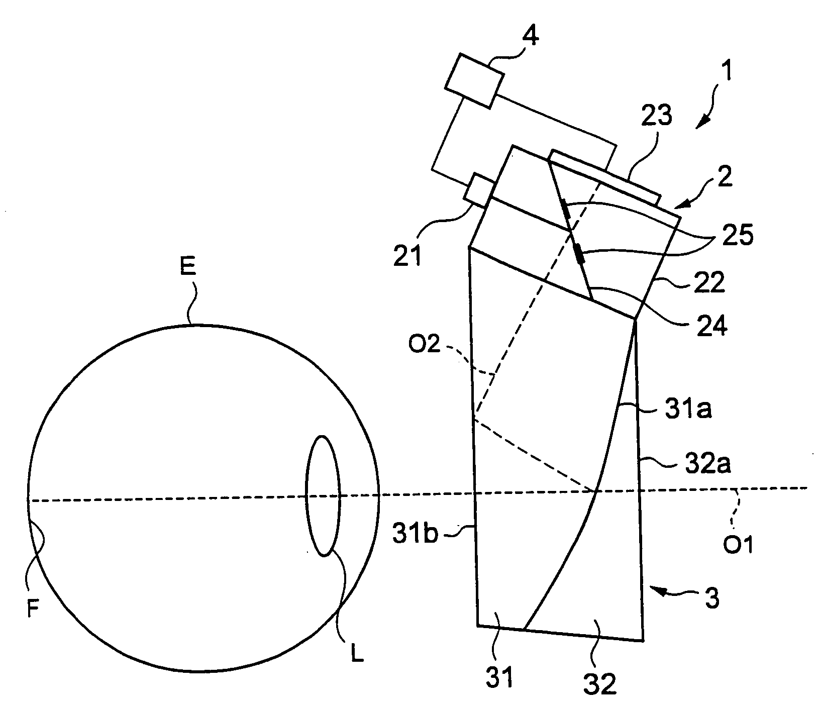
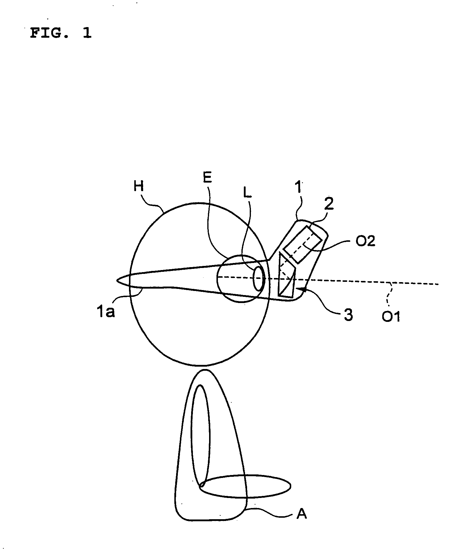
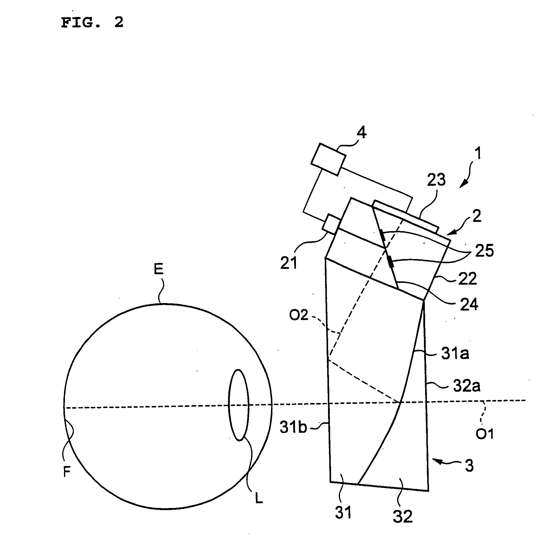
[0028]FIGS. 1 and 2 are structural views showing a refraction measuring instrument 1 according to a first embodiment of the present invention, in which FIG. 1 is a schematic perspective view showing a use state thereof and FIG. 2 is a schematic view showing an inner structure thereof. Each of FIGS. 1 and 2 is a side view, so only the structure of the instrument for the right eye of a subject A is shown therein. However, the same structure is provided for the left eye, so that the refraction of each of the right and left eyes can be measured. Hereinafter, only the structure for the right eye as shown in both the drawings will be described.

[0029] As shown in FIG. 1, the refraction measuring instrument 1 performs the measurement while it is worn on a head H of the subject A through a wearing section 1a. The wearing section 1a is composed of a wearing frame similar to a spectacles, a belt whose size can be adjusted according to a size of ...

second embodiment

[0040] Next, a refraction measuring instrument according to a second embodiment of the present invention will be described. FIG. 3 is a schematic view showing an inner structure of a refraction measuring instrument 101 according to this embodiment. Although not shown, the refraction measuring instrument 101 is provided with a wearing section for enabling the instrument to be worn on the head of the subject and used in the same state as that of the refraction measuring instrument 1 according to the first embodiment.

(Structure of Refraction Measuring Instrument)

[0041] As shown in FIG. 3, the refraction measuring instrument 101 according to this embodiment includes an optical module 102 and a prism section 103. Although not shown, the instrument includes the same calculation control device (calculation means and control means) as that of the refraction measuring instrument 1 according to the first embodiment.

[0042] The optical module 102 (measurement means) for performing refractio...

third embodiment

[0056] When the refraction of the eye to be examined E is measured in real time as described above, the eye movement of the eye to be examined E particularly becomes a problem with respect to measurement accuracy in many cases. For example, when the measurement using retinoscopy is performed by the refraction measuring instrument 1 according to the first embodiment, the measurement accuracy is less affected by small eye movement. However, when the eye movement is large or when an eye position is to be detected with high accuracy using a Hartmann-Shack wavefront sensor, it is necessary to provide any structure for moving the instrument based on the eye movement to ensure the measurement accuracy. With respect to an eye movement measuring method enabling this, there are a method using reflection light on the anterior surface of a cornea, a method using reflection light on the posterior surface of the cornea or the anterior or posterior surface of a crystalline lens, a method of detect...


PUM


Abstract

A refraction measuring instrument for measuring the refraction of an eye to be examined while the subject is viewing an external object in a more natural posture. A measuring light beam from a light source 21 is reflected from a mirror 25, shaped into a beam with a ring cross section, directed to a free curved surface prism 31 along an optical axis O2, reflected from a surface 31b and a beam splitting surface 31a, guided to an eye E along an optical axis O1 together with the visible light from outside the instrument, and form a ring pattern on the fundus F. The measurement beam reflected from the fundus F is received by a CCD 23 through the free curved surface prism 31 and a prism 22, and a ring pattern is imaged. A calculation control device 4 analyzes the imaged ring pattern and calculates the sphericity, the degree of astigmatism, and the astigmatic axis angle. For measurement, the subject A wears the refraction measuring instrument 1 on the head H through a wearing section 1a.

Description

TECHNICAL FIELD [0001] The present invention relates to a refraction measuring instrument for measuring the refraction of an eye to be examined, and more particularly to a refraction measuring instrument capable of measuring the refraction of an eye to be examined while a subject is viewing the surrounding ambience, an image, or the like in a natural posture. BACKGROUND ART [0002] A refraction measuring instrument which is widely used at present normally includes a chin rest on which the chin of a subject is placed and a head rest to which the forehead of the subject abuts (see, for example, JP 11-299733 A) in order to prevent a relative position difference between the subject and the refraction measuring instrument. In such a refraction measuring instrument, the measurement is performed on the subject in an unnatural posture in which the subject slouches and the chin and the forehead are in contact with the chin rest and the head rest, respectively. Therefore, physical and mental b...

Claims


Application Information

Patent Timeline
IPC IPC(8): A61B3/10A61B3/14A61B3/103A61B3/11A61B3/113
CPCA61B3/103
Inventor MIHASHI, TOSHIFUMI
Owner KK TOPCON
Why Eureka
Try Eureka