
Musculosketal loading device

Inactive Publication Date: 2006-09-28
VIBETECH INC
View PDF10 Cites 5 Cited by
  • Summary
  • Abstract
  • Description
  • Claims
  • Application Information

AI Technical Summary

Benefits of technology

[0009] A connecting structure couples the restraint across the tissue to be treated. The device does not require gravity to operate and as a result is expected to have applications in space, such as with astronauts, with those having bone ailments such as bed-ridden patients, persons with osteoporosis or disuse atrophy, athletes, recovering bone cancer patients, and persons with musculoskeletal disorders.

Problems solved by technology

Osteoporosis is a disease characterized by low bone mass and structural deterioration of bone tissue which can seriously impede the ability of osteoporotic bones to provide support and protection for the body.
An increased risk of bone fracture is present in individuals with osteoporosis.
Around 28 million American's suffer from low bone mass or osteoporosis and are at risk of adding to the yearly cost of treatment for the disease.
Bone disuse atrophy is a disease that can also lead to osteoporosis.
While undergoing long flights in space, astronauts suffer from a lack of weight bearing on their bones.
Decreases in bone mass of this magnitude could seriously impede an astronaut's bone health during long duration space flight, such as what will someday be incurred by astronauts on roundtrip missions to Mars or other planets.
The majority of current countermeasures for bone disuse atrophy are not entirely effective.
Mineral and hormone treatments have been administered as attempts to maintain bone mass, but have had little benefit in the long run.
However, some methods of applying mechanical stimuli may be more damaging than good, while others may only partially aid in the maintenance of bone strength.
Because this arrangement relies on gravity, the arrangement does not provide an adjustable load and loses its effectiveness as gravity is reduced.

Method used


Image

  • Musculosketal loading device
  • Musculosketal loading device
  • Musculosketal loading device

Examples


Embodiment Construction

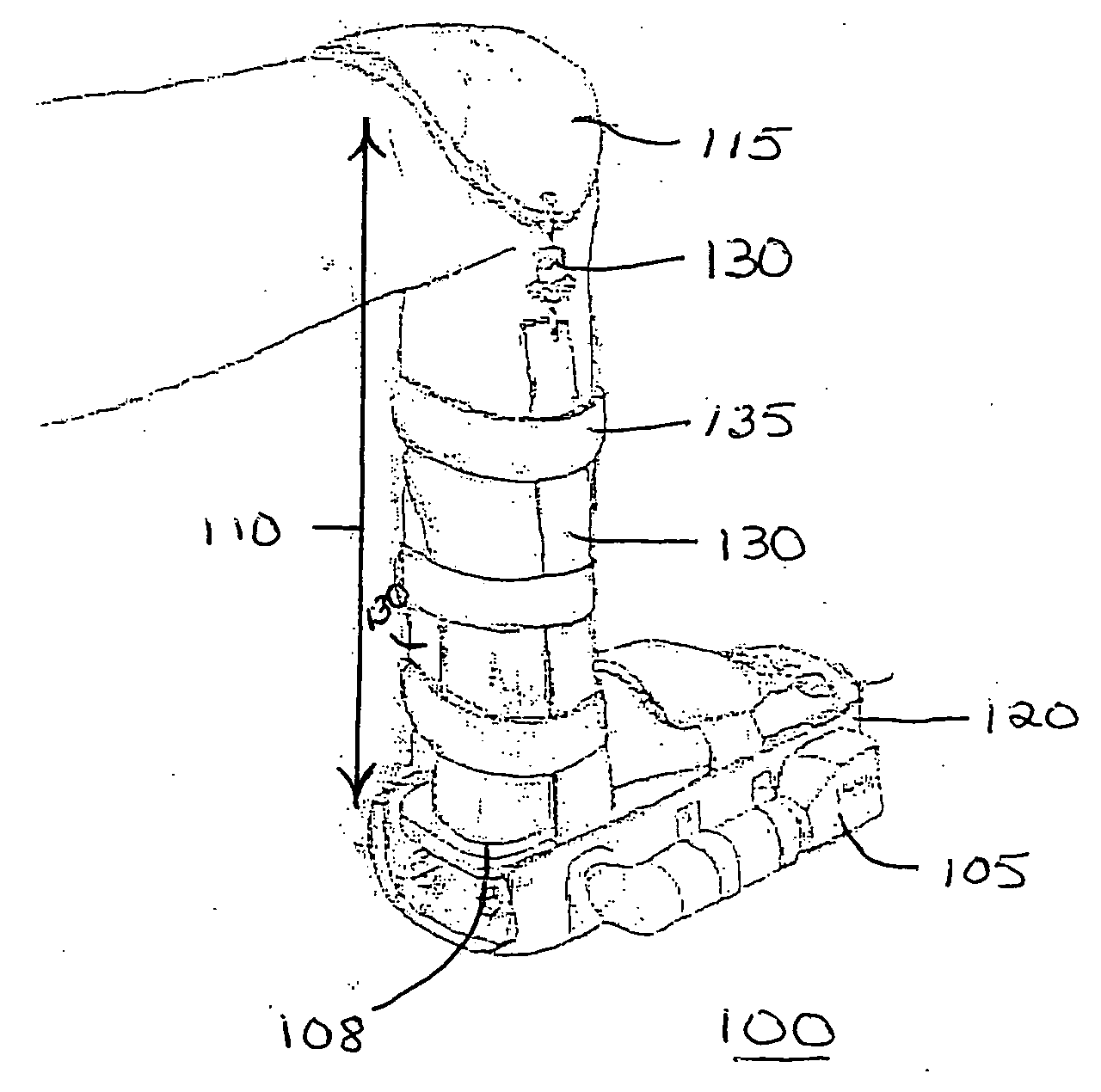
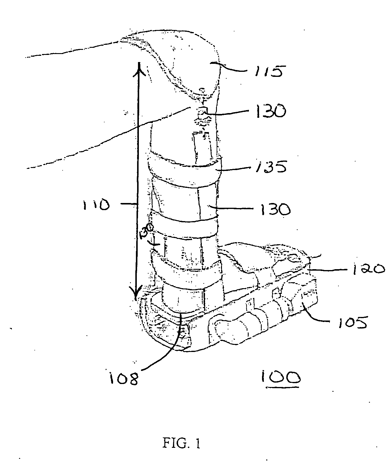
[0023]FIG. 1 illustrates a device 100 for non-invasively mechanically stimulating bone or muscle in a subject, according to an embodiment of the invention. Device 100 can be used to mechanically stimulate an osteogenic effect in bone or the development of muscle. Device 100 includes a vibrational energy generator 105 for applying vibrational energy to a first end 108 of a length of a tissue to be treated 110 which includes bone and / or muscle therein (not shown). The vibrational energy is for inducing strain in at least one region within the length of the tissue 110.

[0024] A restraint 115 is disposed opposite the first end of the length 110 to resist translation of the length during operation of the device 100. Restraint 115 is coupled to connecting structure 130 which couples restraint 115 to the first end of the length of tissue to be treated, such as through connection to frame 120. Connecting structure 130 also provides a compressional or tensile coupling force to the region to ...


PUM


Abstract

A device for non-invasively mechanically stimulating bone or muscle includes a vibrational energy generator for applying vibrational energy to a first end of a length of a tissue which includes bone and / or muscle. The vibrational energy is for inducing strain in at least one region within the length of tissue. A restraint is disposed opposite the first end of the length to resist translation of the length during operation of the device and to provide loading to the bone or muscle. A connecting structure couples the restraint to the vibrational energy generator. The device does not require gravity to operate and as a result is expected to have applications in space, such as with astronauts, with those having bone ailments such as bed-ridden patients, persons with osteoporosis or disuse atrophy, athletes, recovering bone cancer patients, and persons with muscoskeletal disorders.

Description

CROSS REFERENCE TO RELATED APPLICATION [0001] The present application is a continuation of U.S. patent application Ser. No. 10 / 419,005, filed Apr. 18, 2003, which claims the benefit of U.S. provisional patent application No. 60 / 373,546 filed on Apr. 18, 2002, the entirety of which are incorporated herein by reference.STATEMENT REGARDING FEDERALLY SPONSORED RESEARCH [0002] This invention was made with United States Government support from the National Institute of Health through Grant No. 1R15HL67787-01. The United States Government has certain rights in this invention.FIELD OF THE INVENTION [0003] This invention relates generally to non-invasive musculoskeletal loading devices which provide adjustable loading. BACKGROUND OF THE INVENTION [0004] The health of human bones is of enormous importance. Bones provide support and protection for the human body. Osteoporosis is a disease characterized by low bone mass and structural deterioration of bone tissue which can seriously impede the ...

Claims


Application Information

Patent Timeline
IPC IPC(8): A61H1/02A61H1/00A61H5/00A61H23/02
CPCA61H1/006A61H23/0254A61H2201/1418A61H2201/1642A61H2201/5061A61H2205/10A61H2205/106
Inventor LEISMER, JEFFREY M.
Owner VIBETECH INC
Learn More