Critical band additive synthesis of tonal audio signals

Inactive Publication Date: 2006-09-28
LINDEMANN ERIC
View PDF5 Cites 9 Cited by
  • Summary
  • Abstract
  • Description
  • Claims
  • Application Information

AI Technical Summary

Benefits of technology

[0014] Accordingly, an object of the present invention is to provide improved methods and apparatus for additive synthes

Problems solved by technology

While sinusoidal encoding and synthesis provides excellent results for tonal audio signals, the synthesis requires large computational resources because many tonal audio signals may involve one hundred or more individual sinusoids.
While this approach reduces somewhat the computation requirements for synthesis of a large number of parameters, the computation is still expensive and new problems are introduced.
This parameter update rate may be insufficient at higher frequencies.
This approach has the disadvantages of IFFT computation cost especially with multi-channel synthesis.
All of these techniques with the exception of simply

Method used


Image

  • Critical band additive synthesis of tonal audio signals
  • Critical band additive synthesis of tonal audio signals
  • Critical band additive synthesis of tonal audio signals

Examples


first embodiment

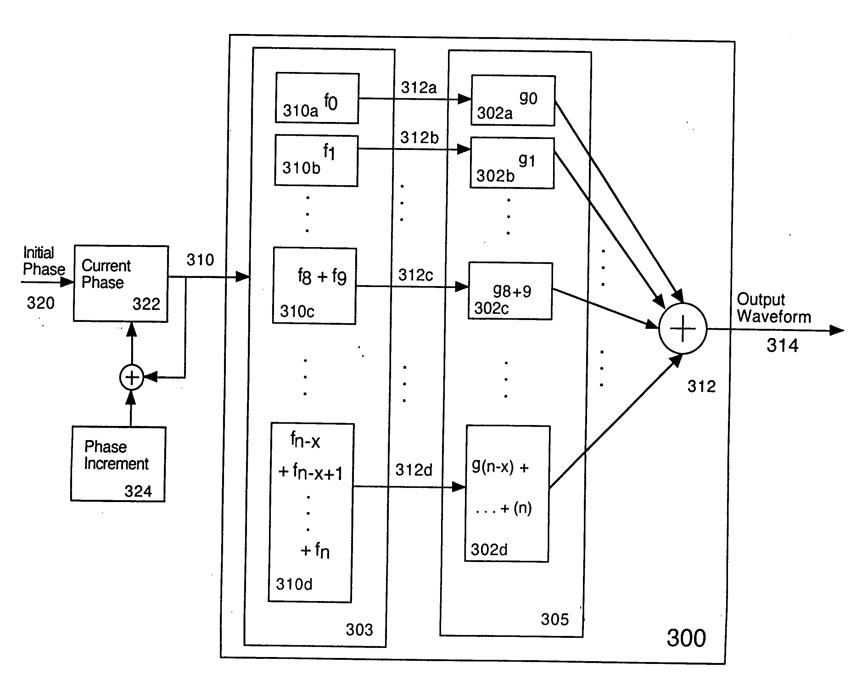
[0036]FIG. 3 is a flow diagram showing a critical band tonal synthesizer 204 according to the present invention. This critical band tonal synthesizer generates the tonal sounds of Synthesizer 200 described above. The embodiment of FIG. 3 is best suited for modeling pitched tonal sounds. A single current phase value 322 is initialized with a single initial phase 320 and incremented by a single phase increment 324. The single current phase 322 is used as an offset into a bank of table lookup oscillators 310. This embodiment is especially efficient for vector processing. Modern CPUs often support efficient vector processing including fetching and calculating multiple values in parallel as long as those values are stored efficiently in memory. Preferably, additive synthesizer 204 interleaves the entries in the tables 310, so that many samples in a row (one from each table in turn) may be read out, rather than skipping around in memory.

[0037] Critical band tonal synthesizer 300 takes adv...

second embodiment

[0067]FIG. 5 is a block diagram illustrating the table lookup / function generator portion of the additive synthesizer of the present invention. This embodiment is very similar to that of FIG. 3, in that a single offset 501 (based upon current phase 322, derived from initial phase 320 and phase increment 324) is the same across all of the table lookup oscillators 510. Critical band signals 512 will have gains applied in gain block 305. Since a single offset 501 is used for all tables 510, it follows that the tables are the same length. An embodiment that is particularly efficient in terms of processing power interleaves the entries in the critical tables 510. This would mean that 24 samples in a row are read out, one from table 510a, one from table 510b, and so on through table 510y, rather than skipping around in memory.

third embodiment

[0068]FIG. 6 is a block diagram illustrating the table lookup / function generator portion of the additive synthesizer of the present invention. In the embodiment of FIG. 6, the first few harmonics are generated by functions generators 610a and 610b. The remaining harmonics are generated as shown in FIG. 5. Function generators 620a and 620b may be second order resonating filters, cordic signal generators, or any similar sinusoidal signal generator.


PUM


Abstract

An efficient synthesizer of tonal audio signals is disclosed. The tonal audio signal synthesizer utilizes additive synthesis of harmonics of the base frequency. Rather than generating and summing all of the individual frequency sinusoidal harmonics as in traditional additive synthesis, critical band signals (comprising multiple harmonics added together) are generated, and the critical bands are summed based upon the Critical Bands resolvable by human hearing. Each critical band signal comprises the combination of from one to many sinusoids, generally of equal amplitude. Generally only a single harmonic is included in the lowest critical band, or the lowest several critical bands. As the frequency increases, the number of harmonics in each critical band increases as well. A gain is applied to each critical band signal.

Description

[0001] This application claims the benefit of U.S. Provisional Application No. 60 / 664,598 filed Jan. 18, 2004, and incorporates it herein by reference. U.S. Pat. No. 6,298,322, issued Oct. 2, 2001 to the present inventor and entitled “Encoding and Synthesis of Tonal Audio Signals Using Dominant Sinusoids and a Vector-Quantized Residual Tonal Signal,” is incorporated herein by reference.FIELD OF THE INVENTION [0002] This invention relates to efficient additive synthesis of tonal audio signals. In particular, the invention relates to critical band additive synthesis of tonal audio signals in a music synthesis system. BACKGROUND OF THE INVENTION [0003] Tonal sounds can be effectively modeled as a sum of sinusoids with time-varying parameters consisting of frequency, amplitude, and phase. The key word here is “effectively” because, in fact, all sounds can be modeled as sums of sinusoids, but the number of sinusoids may be extremely large, and the time-varying sinusoidal parameters may n...

Claims


Application Information

Patent Timeline
IPC IPC(8): G10L13/06
CPCB60N2/07B60N2/0825B60N2/0875B60N2/38G10L19/093G10H1/08G10H7/10G10H2250/621B60N2/075B60N2/686
Inventor LINDEMANN, ERIC
Owner LINDEMANN ERIC
Why Eureka
Try Eureka