Driving unit for driving vehicle by motor

a technology of driving unit and motor, which is applied in the direction of gearing details, electric propulsion mounting, transportation and packaging, etc., can solve the problems of insufficient cooling outside of the coil, insufficient connection of other hoses such as those for cooling water to the inwheel motor, and high heat radiation requirements, so as to achieve the effect of improving cooling performan

Inactive Publication Date: 2006-10-05
TOYOTA JIDOSHA KK +1
View PDF1 Cites 46 Cited by
  • Summary
  • Abstract
  • Description
  • Claims
  • Application Information

AI Technical Summary

Benefits of technology

[0013] An object of the present invention is to provide a driving unit for a vehicle in which cooling performance is improved.

Problems solved by technology

However, since the inwheel motor is placed at a position less likely to catch airflow generated by the vehicle's travel, it requires efficient heat radiation.
Therefore, it is difficult to further connect any other hoses such as those for cooling water to the inwheel motor.
Therefore, the outside of the coil is not sufficiently cooled.
Furthermore, when the lubricating oil is splashed inside the coil, it can enter a gap portion between the rotor and the stator.
If the lubricating oil enters the gap portion between the rotor and the stator, resistance occurs for shearing the lubricating oil, which can disadvantageously increase force loss in rotating the rotor.

Method used


Image

  • Driving unit for driving vehicle by motor
  • Driving unit for driving vehicle by motor
  • Driving unit for driving vehicle by motor

Examples


Embodiment Construction

[0025] An embodiment of the present invention will hereinafter be described in detail with reference to the drawings. The same or similar parts in the drawings are provided with the same reference characters, and the description thereof will not be repeated.

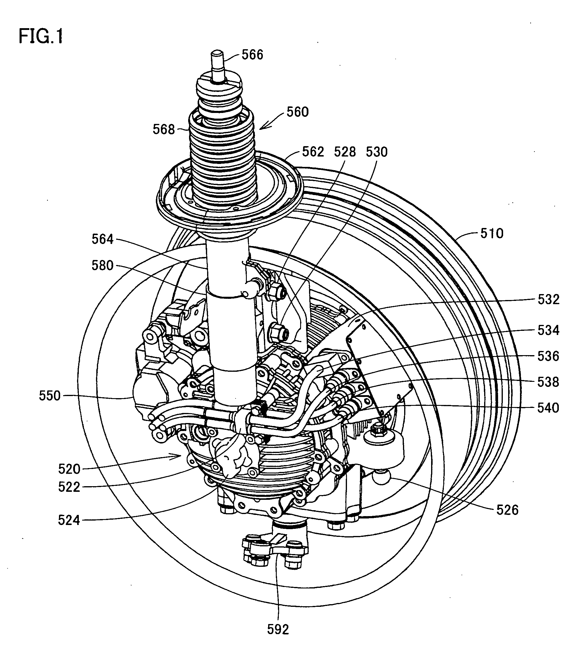
[0026]FIG. 1 is a perspective view of a driving unit according to an embodiment of the present invention.

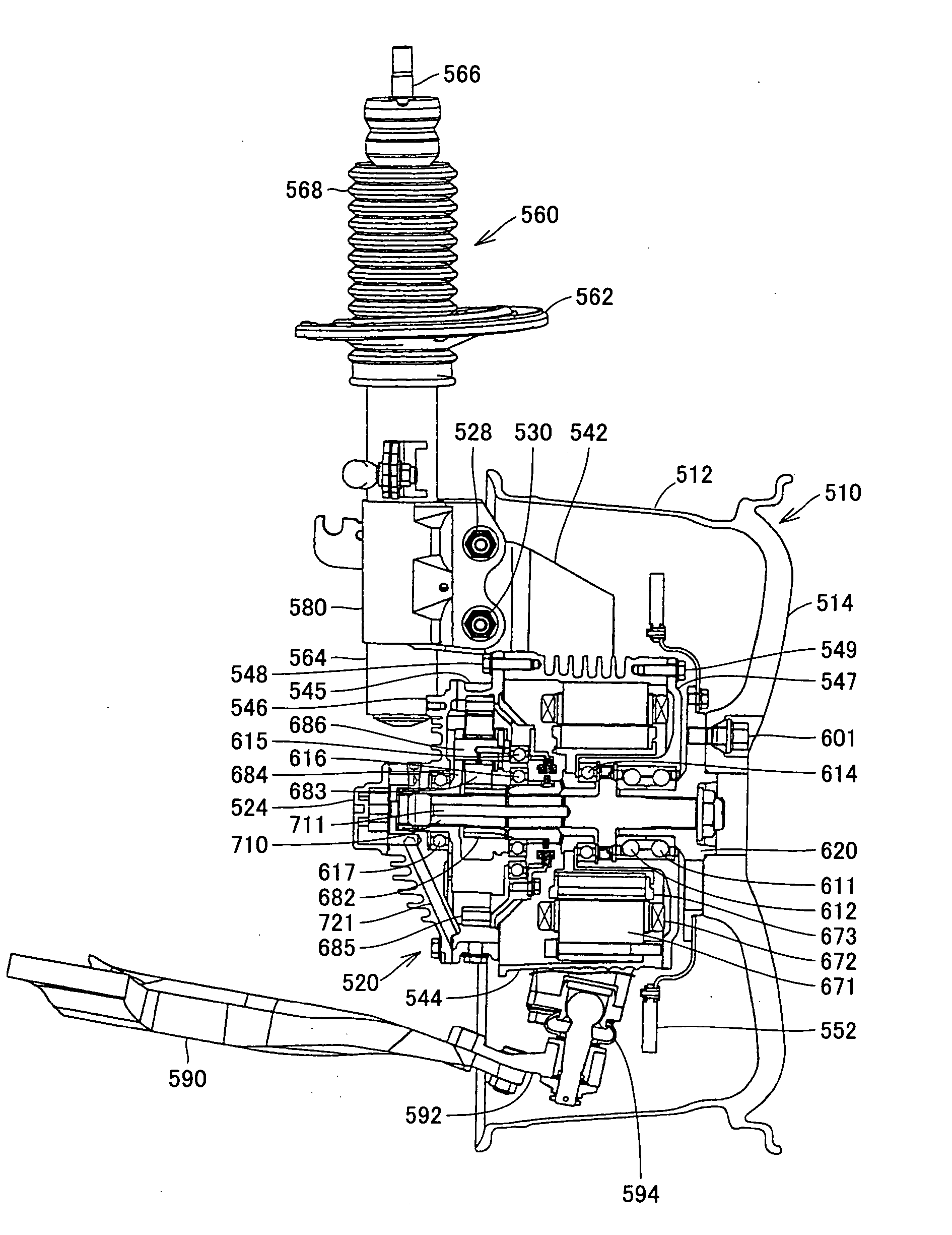
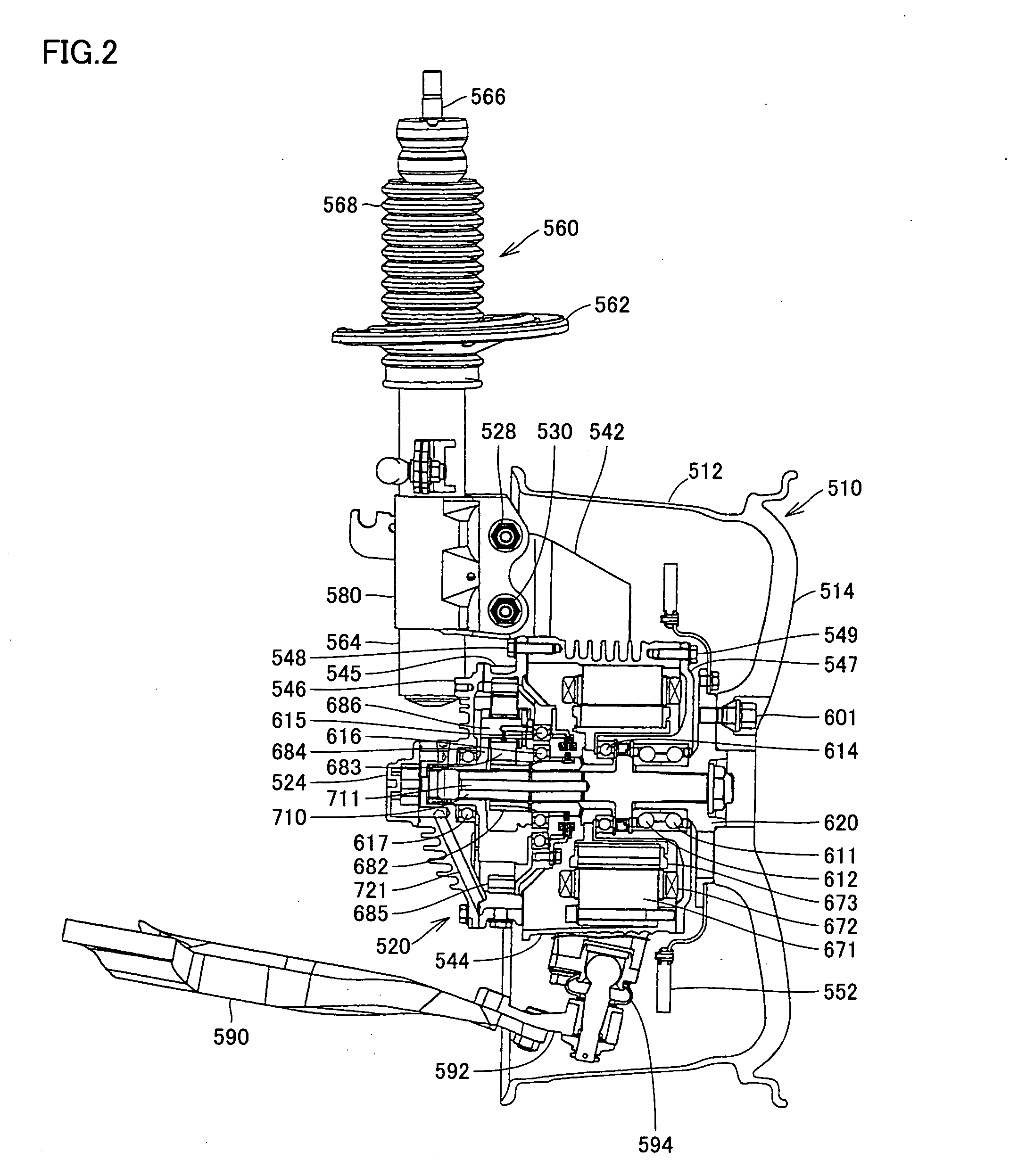
[0027] Referring to FIG. 1, the driving unit includes a wheel 510, an inwheel motor 520 placed in the wheel, and a shock absorber 560 placed at the inwheel motor on the inner, vehicle body side and elongating and contracting in accordance with the vertical movement of wheel 510. Shock absorber 560 includes an outer cylinder 564 in which oil, nitrogen gas, or the like is enclosed, a piston rod 566 where a piston that slides in the outer cylinder is attached to its tip, an absorber cover 568 for covering the piston rod, and a spring sheet 562 on which a spring coil not shown is placed.

[0028] Inwheel motor 520 is provided with...


PUM


Abstract

A bearing for supporting rotation of either of a rotor and a planetary gear is supported by a wall disposed between a motor housing and a gear case room. The wall is provided with an opening allowing lubricating oil splashed by a gear to be splashed onto an upper portion of a stator. Some of the lubricating oil passes through an oil passage placed at a central portion of a shaft and through an oil passage provided at a planetary carrier, and is then splashed through the opening onto an outer periphery of a stator coil. Furthermore, the lubricating oil is also splashed by a pinion gear, and is similarly splashed through the opening onto the stator coil and an inner peripheral wall of the motor housing. Accordingly, the stator coil and the stator core are cooled.

Description

[0001] This nonprovisional application is based on Japanese Patent Application No. 2005-057453 filed with the Japan Patent Office on Mar. 2, 2005, the entire contents of which are hereby incorporated by reference. BACKGROUND OF THE INVENTION [0002] 1. Field of the Invention [0003] The present invention relates to a driving unit, and more particularly, to a driving unit for driving a vehicle by a motor. [0004] 2. Description of the Background Art [0005] In recent years, from the viewpoints of environmental protection and fuel efficiency, attention has been focused on a vehicle whose wheels are driven by an electric motor. Examples of such a vehicle include an electric vehicle, a hybrid vehicle, and a fuel cell vehicle. [0006] As one of driving units to be mounted on such a vehicle, an inwheel motor has been developed. The inwheel motor is a driving motor individually provided inside each of the wheels. The inwheel motor enables easy control of torque in each of the wheels, and is exp...

Claims


Application Information

Patent Timeline
Patent Type & Authority Applications(United States)
IPC IPC(8): B60K1/00B60K7/00F16H57/04H02K5/20
CPCB60K7/0007B60K17/046B60K2001/003H02K9/19H02K7/116H02K7/14F16H57/0457
Inventor MIZUTANI, RYOJITORII, ATSUSHITOJIMA, YUKI
Owner TOYOTA JIDOSHA KK
Why Eureka
Try Eureka