Method of measuring ion beam position

a technology of ion beam and position, which is applied in the direction of optical radiation measurement, beam/ray deflecting arrangement, incandescent lamp details, etc., can solve the problems of non-desirable positive ions, measurement devices that are capable, and other non-desirable ions are also created

Active Publication Date: 2006-10-05
AXCELIS TECHNOLOGIES
View PDF3 Cites 19 Cited by
  • Summary
  • Abstract
  • Description
  • Claims
  • Application Information

AI Technical Summary

Benefits of technology

[0008] The present invention overcomes the limitations of the prior art by providing a system, apparatus, and method for determining a position and angles of incidence of an ion beam in an ion implantation system. Consequently, the following presents a simplified summary of the invention in order to provide a basic understanding of some aspects of the invention. This summary is not an extensive overview of the invention. It is intended to neither identify key or critical elements of the invention nor delineate the scope of the invention. Its purpose is to present some concepts of the invention in a simplified form as a prelude to the more detailed description that is presented later.
[0009] The present invention is directed generally toward an ion implantation system and a measurement apparatus for measuring a position of the ion beam in two orthogonal directions relative to a workpiece. Further, the measured position can be utilized to determine angles of incidence of the ion beam to the workpiece. According to one exemplary aspect of the invention, the ion implantation system comprises an ion implanter operable to form an ion beam and a measurement apparatus, wherein the measurement apparatus further comprises a first elongate sensor and a second elongate sensor associated with a plane of the apparatus. The first elongate sensor, for example, extends in a first direction along the plane of the measurement apparatus, wherein the first elongate sensor is operable to sense one or more characteristics of the ion beam. The second elongate sensor extends along the plane at an angle that is oblique to the first elongate sensor, wherein the second elongate sensor is further operable to sense the one or more characteristics of the ion beam.
[0010] According to another exemplary aspect of the invention, a translation mechanism is provided, wherein the translation mechanism is operably coupled to the ion implanter and the measurement apparatus, and wherein the translation mechanism is operable to translate the measurement apparatus through a path of the ion

Problems solved by technology

Generally, in addition to desired dopant ions being created, other non-desirable positive ions are also created.
However, conventional emittance measurement devices that are capable of measuring emittance in both horizontal and vertical directions are either substa

Method used


Image

  • Method of measuring ion beam position
  • Method of measuring ion beam position
  • Method of measuring ion beam position

Examples


Embodiment Construction

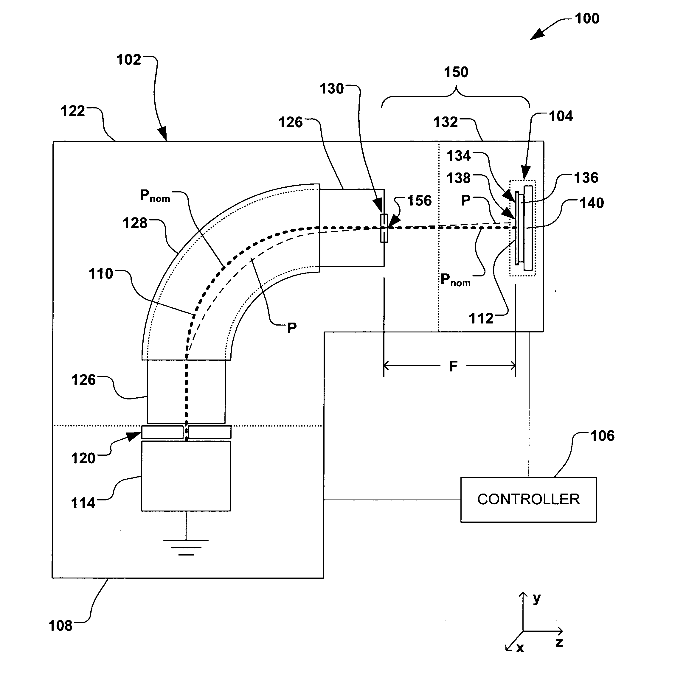
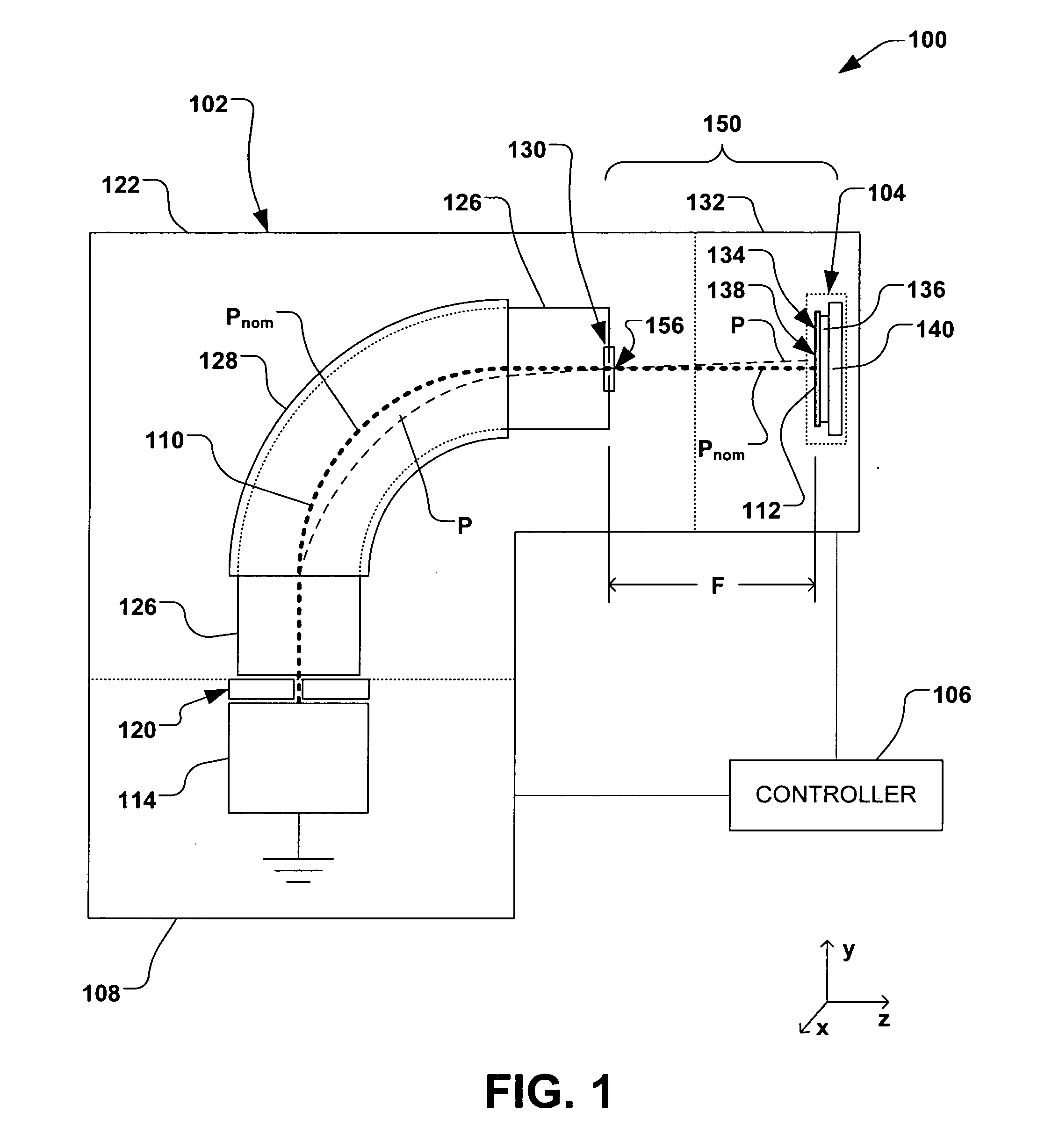
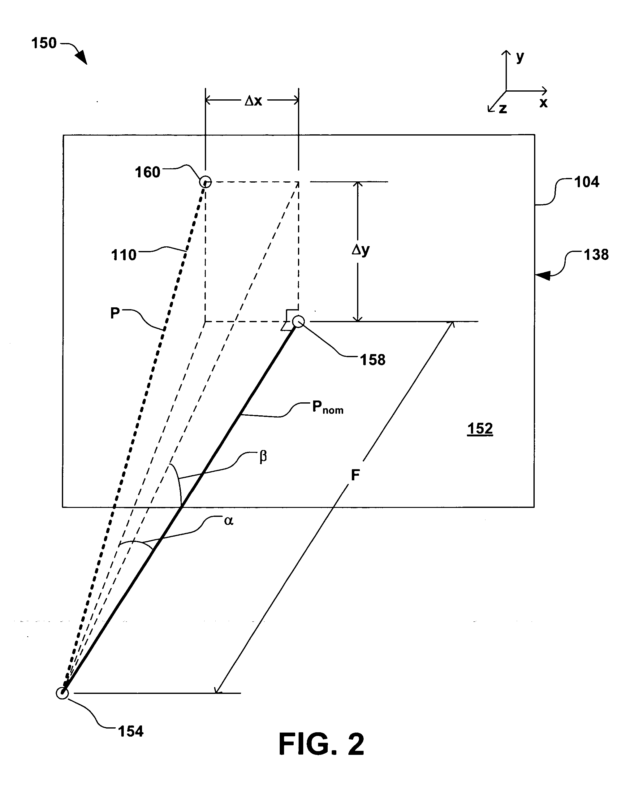
[0019] The present invention is directed generally towards a system, apparatus, and method for measuring a position of an ion beam in two orthogonal directions within an ion implantation system. More particularly, the system, apparatus, and method provide for measuring ion beam position and angles in two dimensions by moving a measurement device through the ion beam along a single axis. Accordingly, the present invention will now be described with reference to the drawings, wherein like reference numerals are used to refer to like elements throughout. It should be understood that the description of these aspects are merely illustrative and that they should not be taken in a limiting sense. In the following description, for purposes of explanation, numerous specific details are set forth in order to provide a thorough understanding of the present invention. It will be evident to one skilled in the art, however, that the present invention may be practiced without these specific detail...


PUM


Abstract

A system, apparatus, and method for determining position and two angles of incidence of an ion beam to a surface of a workpiece is provided. A measurement apparatus having an elongate first and second sensor is coupled to a translation mechanism, wherein the first sensor extends in a first direction perpendicular to the translation, and wherein the second sensor extends at an oblique angle to the first sensor. The first and second elongate sensors sense one or more characteristics of the ion beam as the first and second sensors pass through the ion beam at a respective first time and a second time, and a controller is operable to determine a position and first and second angle of incidence of the ion beam, based, at least in part, on the one or more characteristics of the ion beam sensed by the first sensor and second sensor at the first and second times.

Description

FIELD OF THE INVENTION [0001] The present invention relates generally to ion implantation systems, and more specifically to a system, apparatus, and method for measuring a position and angle of incidence of an ion beam. BACKGROUND OF THE INVENTION [0002] In the manufacture of semiconductor devices and other products, ion implantation systems are used to impart impurities, known as dopant elements, into semiconductor wafers, display panels, or other workpieces. Typical ion implantation systems or ion implanters treat a workpiece with an ion beam in order to produce n- or p-type doped regions, or to form passivation layers in the workpiece. When used for doping semiconductors, the ion implantation system injects a selected ion species to produce the desired extrinsic material. Typically, dopant atoms or molecules are ionized and isolated, sometimes accelerated or decelerated, formed into a beam, and swept across a wafer. For example, the ion beam may be manipulated to “scan” the wafer...

Claims


Application Information

Patent Timeline
IPC IPC(8): H01J37/08
CPCH01J37/244H01J37/304H01J37/3045H01J37/3171H01J2237/24405H01J2237/31703H01J2237/24528H01J2237/24542H01J2237/30405H01J2237/30411H01J2237/31701H01J2237/24507H01L21/265
Inventor RAY, ANDREW M.
Owner AXCELIS TECHNOLOGIES
Why Eureka
Try Eureka