Power management controller

a power management controller and power supply technology, applied in the direction of emergency power supply arrangements, safety/protection circuits, light to electrical conversion, etc., can solve the problems of depleting the battery used to start the vehicle, the additional battery may not provide the needed current for a sufficient period of time, and the additional battery may not provide the needed current for the engine load or ancillary load of the other powertrain. to achieve the effect of facilitating the flow of curren

Inactive Publication Date: 2006-10-05
KOLD BAN INT
View PDF16 Cites 23 Cited by
  • Summary
  • Abstract
  • Description
  • Claims
  • Application Information

AI Technical Summary

Benefits of technology

[0007] A charging system includes cables, a switch, and a wireless receiver. A first cable is coupled to a vehicle to conduct current. A second cable is coupled to the vehicle to conduct a separate current. The switch is coupled to the first and second cables to control current flow to the vehicle. A wireless receiver coupled to the switch facilitates the flow of current to the vehicle when the wireless receiver receives an incoming signal from a transmitter.

Problems solved by technology

Engine management, audio, telematics, occupant safety, console, and other systems are consuming the power generated by a vehicle's electrical system.
While a vehicle's charging system may support high electrical loads when the engine is running, when the engine is turned off, the parasitic drain of these loads may deplete the battery used to start that vehicle.
Unfortunately, in some systems, the additional battery may not provide the needed current to support the engine load or ancillary loads of the other powertrain and in-vehicle systems.
Moreover, the added battery may not provide the needed current for a sufficient period of time to start the vehicle.
If it does not have sufficient power, the dead or weakened battery will draw power from the added battery.
When connected for an extended period of time, the added battery may also become depleted.
The reduction in power dissipates energy in the form of heat, which lowers the efficiency of the charging system.
Because of its low efficiency, some supplemental supplies need bulky and expensive heat sinks and cooling fans, which may decrease the output of the supply and create a bulky and heavy device that is difficult to use.
Moreover, when a high current is needed, some supplemental supplies may not provide the needed current long enough to start a vehicle.

Method used


Image

  • Power management controller
  • Power management controller
  • Power management controller

Examples


Embodiment Construction

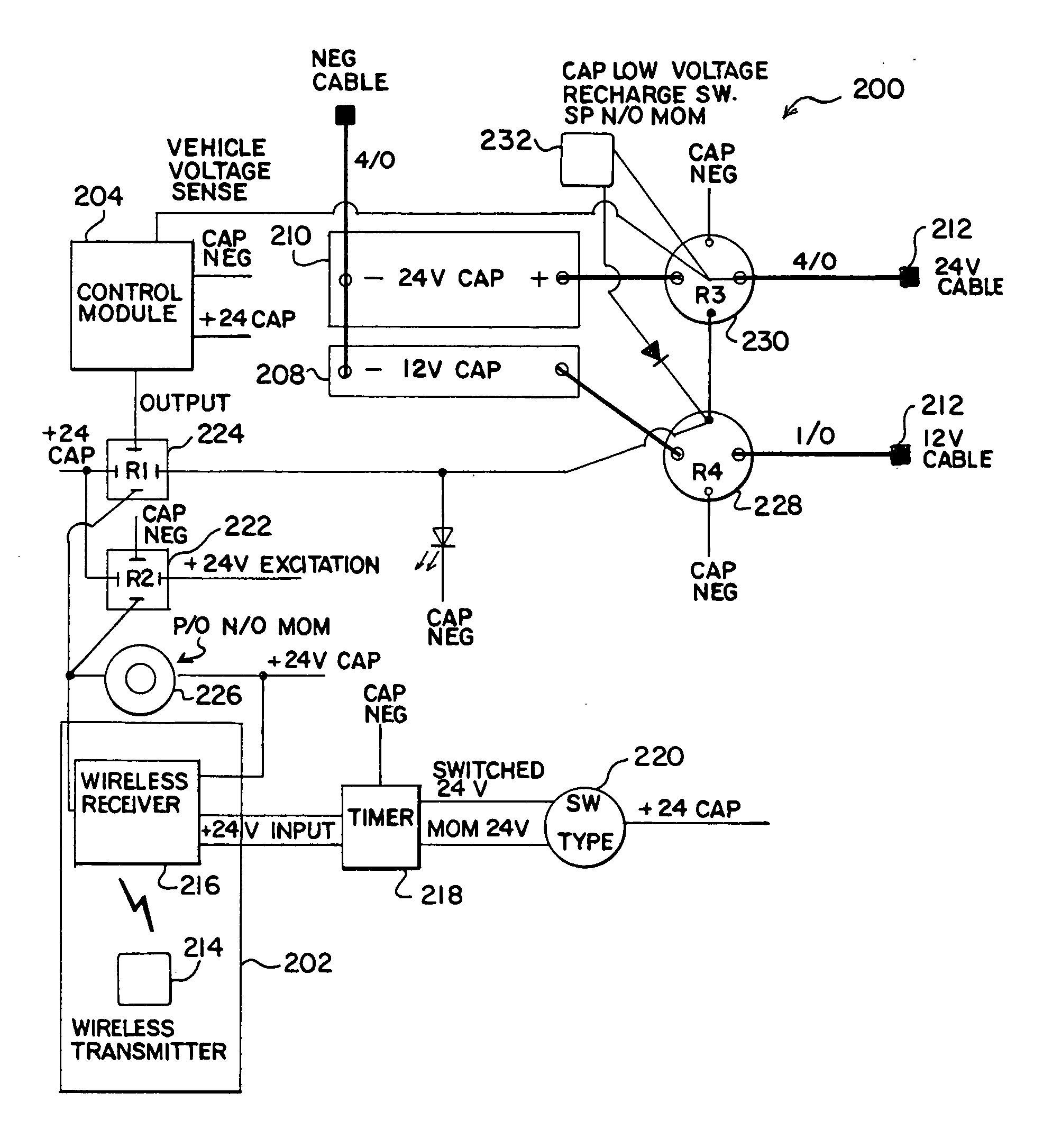
[0019] A portable charging system is capable of sourcing power to start a vehicle and support other vehicle systems. The system may provide one, two, or more separate voltage ranges. Some voltage ranges maybe suitable to start a vehicle such as a passenger vehicle (e.g., a car), a truck, a bus, or heavy duty vehicles. Other voltage ranges maybe suitable to turn on engine management, audio, telematics, occupant safety, consoles, and other systems or combinations of systems. The charging system may include a wireless interface, audio and / or visual reverse polarity protection, and a power management system.

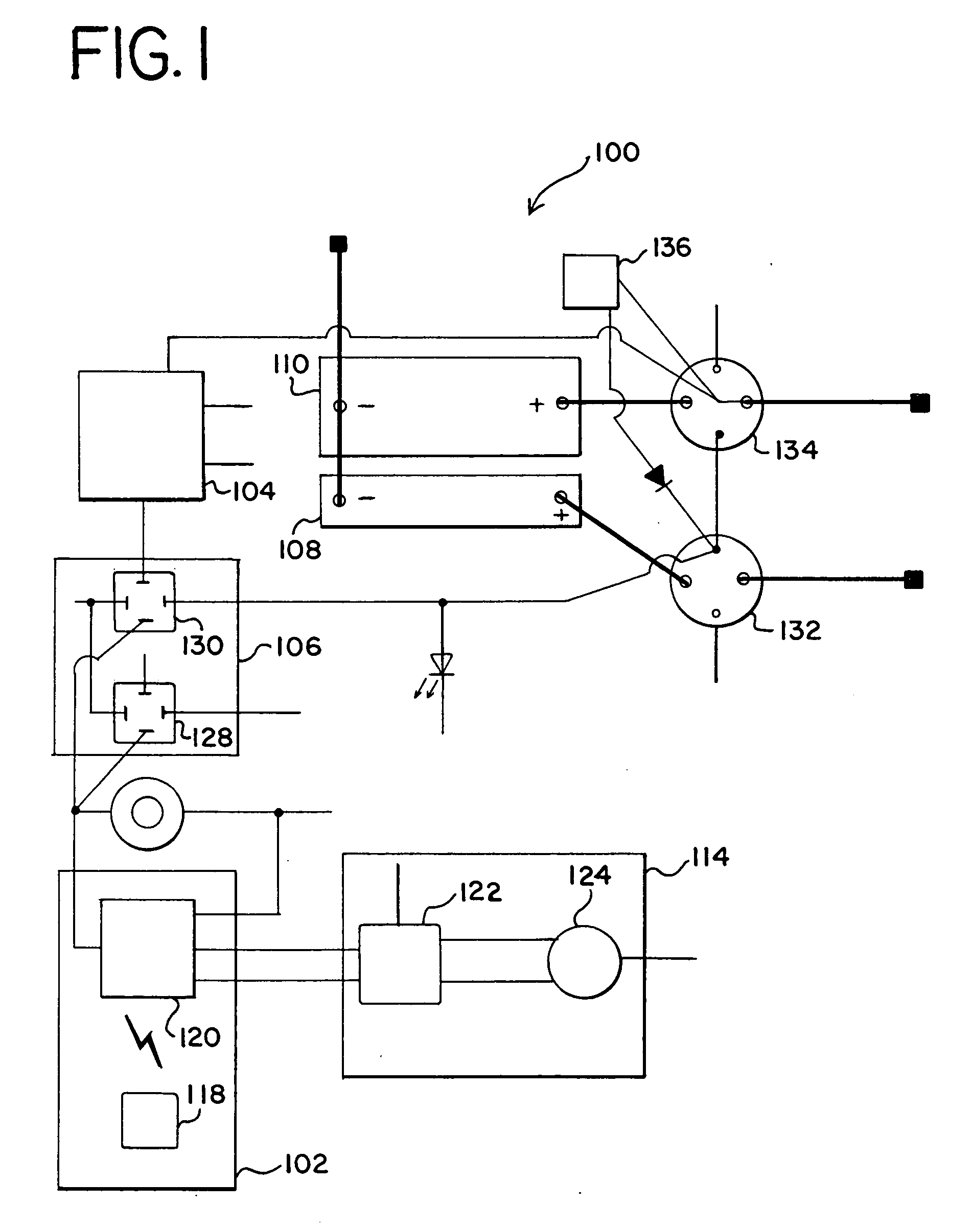
[0020]FIG. 1 is a partial block diagram of the portable charging system 100. The portable charging system 100 includes a wireless controller 102, a second controller or control module 104, electrical and mechanical switches, and a plurality of boost modules 108 and 110. The wireless controller 102 sends and receives data through radio, optical signaling (e.g., infrared) or some othe...


PUM


Abstract

A charging system includes cables, a switch, and a wireless receiver. A first cable is coupled to a vehicle to conduct current. A second cable is coupled to the vehicle to conduct a separate current. The switch is coupled to the first and second cables to control current flow to the vehicle. A wireless receiver coupled to the switch facilitates the flow of current to the vehicle when the wireless receiver receives an incoming signal from a transmitter. The method of charging a vehicle comprises coupling the switch to the first cable and the second cable; coupling a first and second boost module to the switch; coupling a controller to the first and second boost module to control the flow of current to the vehicle when a threshold voltage is detected; and coupling a wireless receiver to the switch to facilitate current flow to the vehicle when the wireless receiver receives an incoming signal and a correct polarity is detected.

Description

BACKGROUND OF THE INVENTION [0001] 2. Technical Field [0002] The inventions relate to charging systems, and more particularly, to energy delivery systems that are capable of delivering current to a vehicle. [0003] 3. Related Art [0004] The demand for electric power in passenger vehicles, cars, trucks, and buses is increasing. Engine management, audio, telematics, occupant safety, console, and other systems are consuming the power generated by a vehicle's electrical system. Many electric systems must support engine, body control, and interior systems when an engine is running. While a vehicle's charging system may support high electrical loads when the engine is running, when the engine is turned off, the parasitic drain of these loads may deplete the battery used to start that vehicle. [0005] When a battery is dead or weakened, it is sometimes necessary to recharge the battery to a level that can be used to start a vehicle. One common way of recharging a battery is by jumping it wit...

Claims


Application Information

Patent Timeline
Patent Type & Authority Applications(United States)
IPC IPC(8): H02J7/00
CPCB60L3/0069Y02E60/721B60L8/003B60L11/1816B60L11/1824B60L11/185B60L2230/16B60L2250/10B60L2250/16H02J7/0031H02J7/0034H02J9/005Y02T10/7005Y02T10/7083Y02T10/7088Y02T10/92Y02T90/121Y02T90/128Y02T90/14Y02T90/163B60L11/1842Y04S10/126B60L3/04B60L53/11B60L53/14B60L53/305B60L55/00Y02E60/00Y02T10/70Y02T10/7072Y02T90/12Y02T90/16
Inventor SOLBERG, DEAN R.
Owner KOLD BAN INT
Why Eureka
Try Eureka