Variable gain amplifier, mixer and quadrature modulator using the same

a technology of amplifier and quadrature, applied in the direction of amplifier with semiconductor devices only, amplifier with semiconductor devices/discharge tubes, amplifier control details, etc., can solve the problems of increasing saturation input level, inability to conduct continuous control thereon, and inability to change the dissipation current for each gain, etc., to achieve low distortion, low dissipation power, and low distortion

Inactive Publication Date: 2006-10-05
PANASONIC CORP
View PDF8 Cites 17 Cited by
  • Summary
  • Abstract
  • Description
  • Claims
  • Application Information

AI Technical Summary

Benefits of technology

[0040] A variable gain amplifier according to the present invention includes a voltage-to-current converter for converting an input voltage into a current, a current amplifier for amplifying the current, a current-to-voltage converter for converting the current amplified by the current amplifier into a voltage, and a controller for controlling an amplification factor of the current amplifier in accordance with a gain control signal. Therefore, the variable gain amplifier can satisfy the three features of low dissipation power, low distortion, and gain continuity simultaneously.
[0041] A mixer according to the present invention includes a voltage-to-current converter for converting an input voltage into a current, a current amplifier for amplifying the current converted by the voltage-to-current converter, a controller for controlling an amplification factor of the current amplifier in accordance with a gain control signal externally inputted, a mixing unit for converting a frequency of the current amplified by the current amplifier, and a current-to-voltage converter for converting the current with its frequency converted by the mixing unit into a voltage. Therefore, the mixer can satisfy the three features of low dissipation power, low distortion, and gain continuity simultaneously.
[0042] A quadrature modulator according to the present invention includes a pair of mixers, an addition section for adding up output currents of the mixers, and a current-to-voltage converter for converting an output current of the addition section into a voltage, wherein each mixer has a voltage-to-current converter for converting an input voltage into a current, a current amplifier for amplifying the current converted by the voltage-to-current converter, a controller for controlling an amplification factor of the current amplifier in accordance with a gain control signal, and a mixing unit for converting a frequency of the current amplified by the current amplifier, in accordance with a gain control signal. Therefore, the quadrature modulator can satisfy the three features of low dissipation power, low distortion, and gain continuity simultaneously.

Problems solved by technology

However, a variable gain amplifier in which a gain is controlled by a gain control circuit having a plurality of differential amplifiers has a disadvantage that a dissipation current cannot be changed for each of the gains.
Another variable gain amplifier having two differential amplifier has a disadvantage that, although a saturation input level is low at most of intermediate level gains, the saturation input level increases if an influence of the first differential amplification circuit is reduced due to an increase in bias current of the second differential amplification circuit having a smaller gain, that is, the saturation input level fluctuates.
A further variable gain amplifier for controlling a quantity of a current by changeover of switches has a disadvantage that it can conduct only discrete gain control on an externally applied gain control voltage but cannot conduct continuous control thereon.
That is, the conventional variable gain amplifiers have a problem that they cannot satisfy the above-described three features of: (1) low dissipation power that low dissipation power can be set if a gain is low and hence an output level is low, (2) low distortion that a saturation input level remains unchanged even if a gain changes, and (3) gain continuity that a continuous gain can be ensured.

Method used


Image

  • Variable gain amplifier, mixer and quadrature modulator using the same
  • Variable gain amplifier, mixer and quadrature modulator using the same
  • Variable gain amplifier, mixer and quadrature modulator using the same

Examples


first embodiment

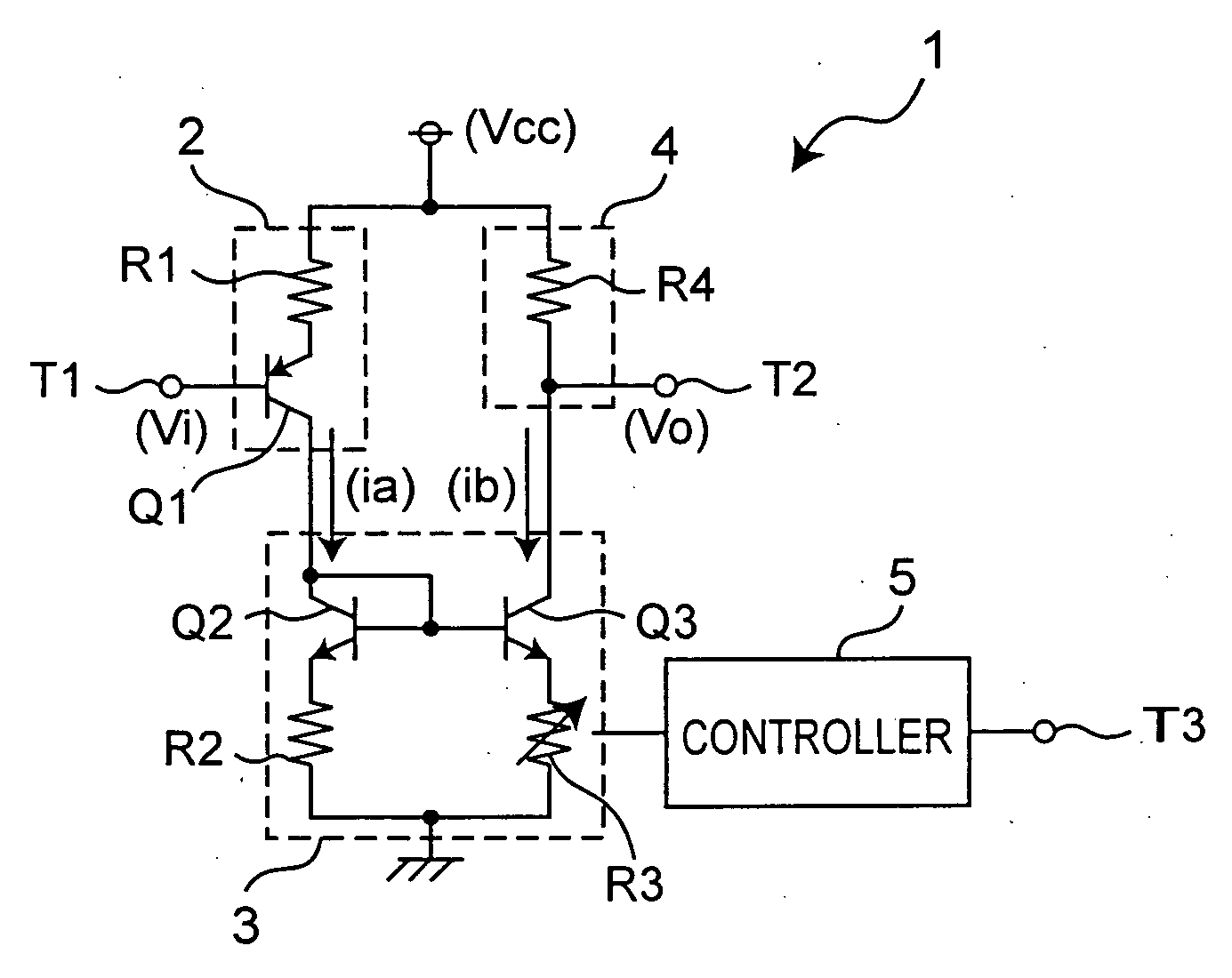
[0061]FIG. 1 is a circuit diagram showing a configuration example of a variable gain amplifier according to the first embodiment of the present invention. This variable gain amplifier amplifies an input voltage at a variable gain and outputs the resultant voltage. As shown in FIG. 1, the variable gain amplifier 1 includes a voltage-to-current converter 2, a current amplifier 3, a current-to-voltage converter 4, and a controller 5. The voltage-to-current converter 2 converts an input voltage into a current. The current amplifier 3 amplifies the current converted by the voltage-to-current converter 2. The current-to-voltage converter 4 converts the current amplified by the current amplifier 3 into a voltage. The controller 5 changes an amplification factor of the current amplifier 3 in accordance with a gain control signal inputted from an outside.

[0062] The following describes in more detail the configuration of the variable gain amplifier 1. The voltage-to-current converter 2 inclu...

second embodiment

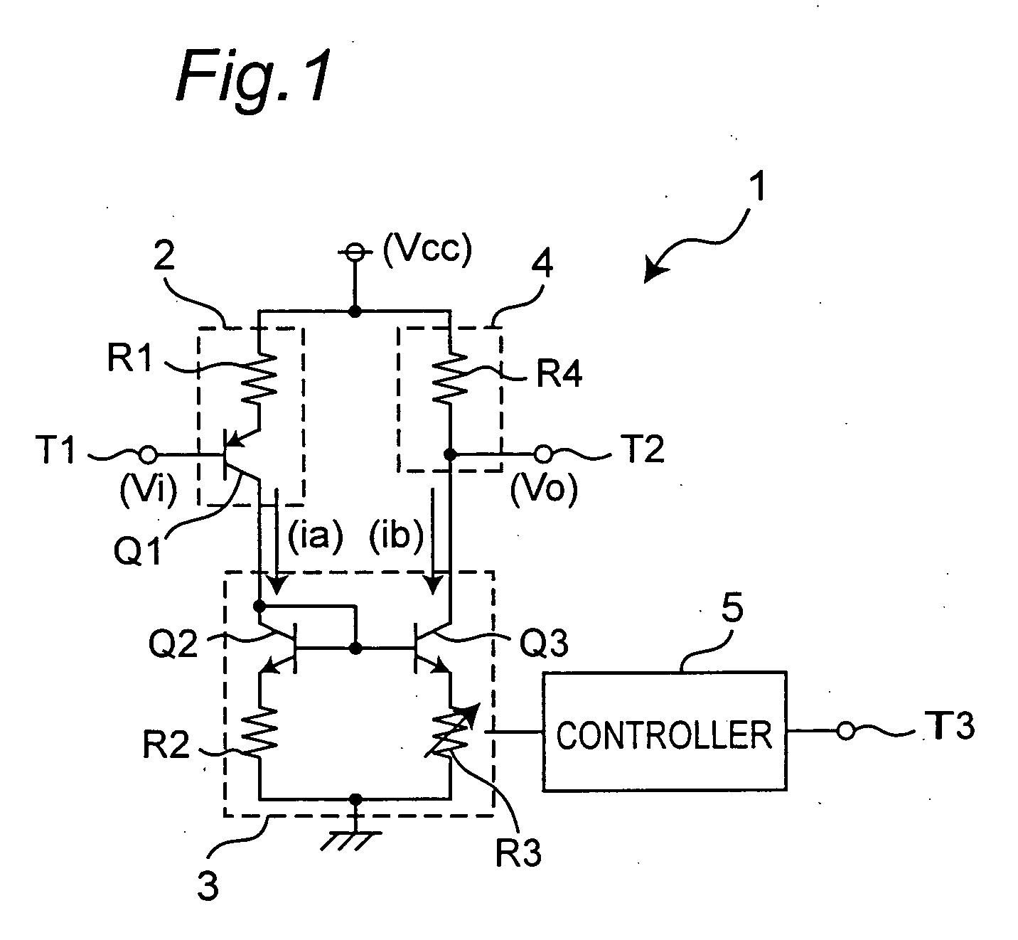
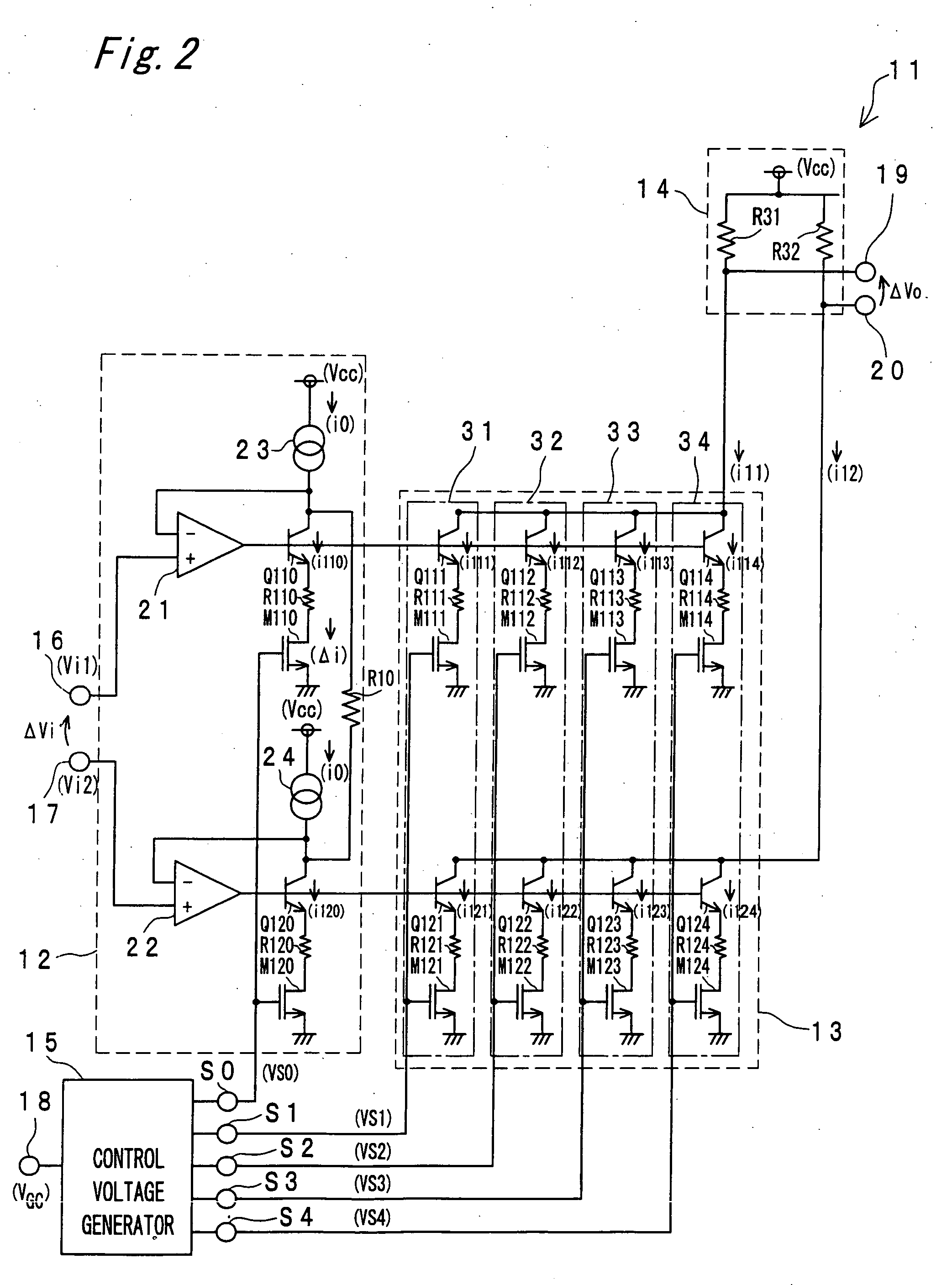
[0072]FIG. 2 is a circuit diagram showing a configuration example of a variable gain amplifier according to the second embodiment of the present invention. As shown in FIG. 2, a variable gain amplifier 11 according to the second embodiment includes a voltage-to-current converter 12, a current amplifier 13, a current-to-voltage converter 14, and a control voltage generator 15. The voltage-to-current converter 12 includes two input terminals 16 and 17 to which input signals are inputted respectively from an outside, and the control voltage generator 15 includes one input terminal 18 to which a gain control signal is inputted from an outside. The current-to-voltage converter 14 converts currents outputted from the current amplifier 13 into voltages and generates the resultant voltages through two output terminals 19 and 20 thereof, respectively. In this arrangement, the control voltage generator 15 constitutes a controller. This variable gain amplifier 11 amplifies the voltages inputte...


PUM


Abstract

A variable gain amplifier includes a voltage-to-current converter for converting the input voltage to a current, a current amplifier for amplifying the current converted by the voltage-to-current converter, a current-to-voltage converter for converting the current amplified by the current amplifier into a voltage, and a controller for controlling an amplification factor of the current amplifier.

Description

BACKGROUND OF THE INVENTION [0001] 1. Field of the Invention [0002] The present invention relates to a variable gain amplifier for use in such as a transmission section of, for example, a CDMA wireless terminal, and a mixer and a quadrature modulator that use such a variable gain amplifier. [0003] 2. Description of the Related Art [0004] As a code division multiple access (CDMA) scheme has come to be utilized more and more, research and development has been greatly advancing on a radio that accommodates CDMA (hereinafter referred to as “CDMA wireless terminal”). For a transmission section of the CDMA wireless terminal, it is indispensable to conduct transmission power control of 70 dB or more, so that a variable gain amplifier plays a major role in this power control. The variable gain amplifier for use in the transmission section has requirements of (1) low dissipation power, (2) low distortion, and (3) ensuring gain continuity. Specifically, “low dissipation power” means that it i...

Claims


Application Information

Patent Timeline
Patent Type & Authority Applications(United States)
IPC IPC(8): H03G3/12
CPCH03G1/0088H03G1/007
Inventor KOJIMA, IWAO
Owner PANASONIC CORP
Why Eureka
Try Eureka