Substrate for organic electroluminescent element, and organic electroluminescent element

a technology of organic electroluminescent elements and substrates, which is applied in the direction of photomechanical devices, photomechanical devices, chemistry apparatuses and processes, etc., can solve the problems of high cost, high yield and cost, and the inability to form highly precise patterns, etc., to achieve convenient and fast production, convenient production and easy production

Inactive Publication Date: 2006-10-05
DAI NIPPON PRINTING CO LTD
View PDF2 Cites 4 Cited by
  • Summary
  • Abstract
  • Description
  • Claims
  • Application Information

AI Technical Summary

Benefits of technology

[0015] According to the present invention, the organic EL layer can be formed by utilizing the pattern with the wettability of the wettability changeable layer of the substrate for an organic EL element changed. Therefore, an organic EL element having the preferable light emission characteristics can be formed efficiently in a simple process.
[0016] According to the present invention, the wettability of the photocatalyst containing layer can be changed in a highly precise pattern ...

Problems solved by technology

However, the photolithography method involves a problem of the process complication and the high cost, and furthermore, the mask deposition method involves a problem of the yield and the cost due to the need of the expensive vacuum apparatus.
Accordingly, a problem is involved in that a highly precise pattern can hardly be formed.
Moreover, according to such a method, when the film thickness of the wettability changeable...

Method used


Image

  • Substrate for organic electroluminescent element, and organic electroluminescent element
  • Substrate for organic electroluminescent element, and organic electroluminescent element
  • Substrate for organic electroluminescent element, and organic electroluminescent element

Examples


first embodiment

1. First Embodiment

[0103] First, a first embodiment of the organic EL element of the present invention will be explained. The organic EL element of the first embodiment provides an organic electroluminescent element comprising an organic electroluminescent layer formed on the photocatalyst containing layer of the substrate for an organic electroluminescent element of the first embodiment, and

[0104] a counter electrode layer formed on the organic electroluminescent layer.

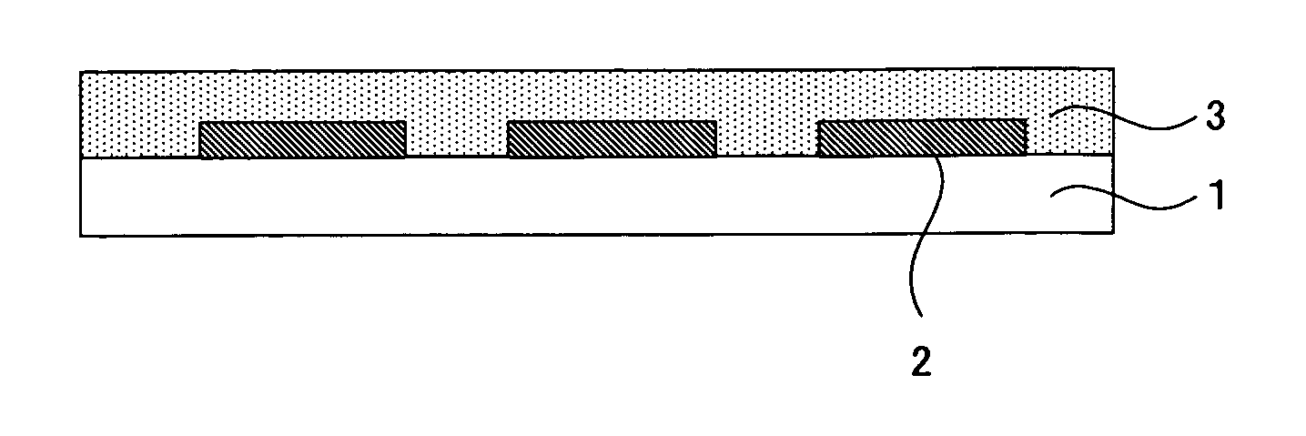
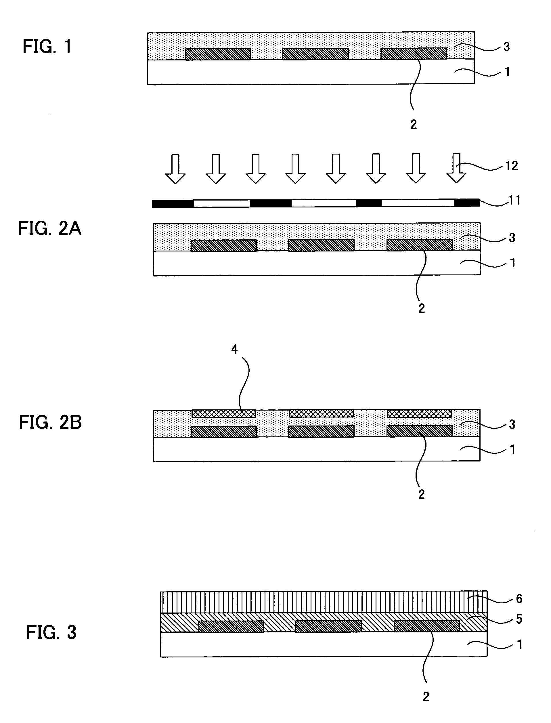
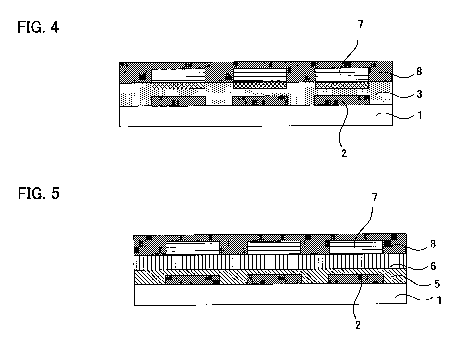
[0105] For example, as shown in FIG. 4, the organic EL element of this embodiment comprises abase material 1, an electrode layer 2 formed in a pattern on the base material 1, a photocatalyst containing layer 3 formed on the electrode layer 2, an organic EL layer 7 formed on the photocatalyst containing layer 3, and a counter electrode layer 8 formed on the organic EL layer.

[0106] According to this embodiment, since the photocatalyst containing layer to have the wettability change by the action of the photocatalyst...

second embodiment

2. Second Embodiment

[0141] The second embodiment of the organic EL element of the present invention provides an organic electroluminescent element comprising

[0142] an organic electroluminescent layer formed on the wettability changeable layer of the substrate for an organic electroluminescent element of the second embodiment mentioned above, and a counter electrode layer formed on the organic electroluminescent layer.

[0143] For example as shown in FIG. 5, the organic EL element of this embodiment comprises a base material 1, an electrode layer 2 formed in a pattern on the base material 1, a photocatalyst processing layer 5 formed on the electrode layer 2, a wettability changeable layer 6 formed on the photocatalyst processing layer 5, an organic EL layer 7 formed on the wettability changeable layer 6, and a counter electrode layer 8 formed on the organic EL layer 7.

[0144] According to this embodiment, since the wettability changable layer to have the wettability change by the act...

examples

[0149] Hereinafter, with reference to the examples, the present invention will be explained more specifically.


PUM

PropertyMeasurementUnit
Timeaaaaaaaaaa
Timeaaaaaaaaaa
Electric propertiesaaaaaaaaaa

Abstract

The object of the present invention is to provide a substrate for an organic EL element capable of forming an organic EL layer efficiently in a highly precise pattern in a short period of time, and an organic EL element having the preferable electric characteristics. To attain the object, the invention provides a substrate for an organic electroluminescent element comprising a base material, an electrode layer formed in a pattern on the base material, and a photocatalyst containing layer formed to cover the electrode layer and contains a photocatalyst and a binder so as to show the wettability change by the action of the photocatalyst accompanied by the energy irradiation, wherein the photocatalyst containing layer contains a portion with the signal intensity of the electron spin resonance spectrum derived from the hydroxy radical increased to 1,000 times or more in 1 second within 600 seconds of the start of the irradiation of the ultraviolet ray at the time of measuring the electron spin resonance spectrum while irradiating the ultraviolet ray.

Description

BACKGROUND OF THE INVENTION [0001] 1. Field of the Invention [0002] The present invention relates to an organic electroluminescent element used preferably for various kinds of displays, light emitting elements, or the like, and a substrate for an organic electroluminescent element used for the production thereof. [0003] 2. Description of the Related Art [0004] Conventionally, in the production method for an organic electroluminescent (hereinafter, also referred to as “organic EL”) element, an organic EL layer is formed by the photolithography method or the mask deposition method. However, the photolithography method involves a problem of the process complication and the high cost, and furthermore, the mask deposition method involves a problem of the yield and the cost due to the need of the expensive vacuum apparatus. [0005] Therefore, as a method for patterning the organic EL layer, a method of using a photocatalyst has been proposed recently (see the official gazette of the Japane...

Claims


Application Information

Patent Timeline
IPC IPC(8): B32B19/00
CPCH01L51/56H01L51/0004H10K71/13H10K71/00G03F7/004H10K50/80
Inventor ITOH, KIYOSHI
Owner DAI NIPPON PRINTING CO LTD
Why Eureka
Try Eureka