Methods and apparatus for reducing spurious signals in implantable medical devices caused by x-ray radiation

a technology of x-ray radiation and spurious signals, applied in the field of implantable medical devices, can solve the problems of increasing the complexity and sophistication of the imds, the imds are vastly more sophisticated and complex, and the imds are capable of performing significantly more complex tasks

Inactive Publication Date: 2006-10-05
MEDTRONIC INC
View PDF7 Cites 9 Cited by
  • Summary
  • Abstract
  • Description
  • Claims
  • Application Information

AI Technical Summary

Problems solved by technology

Today's state-of-the-art IMDs are vastly more sophisticated and complex than earlier ones, and are capable of performing significantly more complex tasks.
As the functional sophistication and complexity of IMDs have increased over the years, however, they have also been found to be vulnerable to more sophisticated and complex sources of interference.
In particular, conventional IMDs have been found to be vulnerable to electromagnetic interference signals produced for example by magnetic resonance imaging (MRI) devices during a magnetic resonance imaging (MRI) scanning session.
The inventors have discovered that x-ray radiation exposure can negatively affect both the sensing amplifiers (causing so-called over-sensing), the amplifiers used to collect EGMs, the clock monitor circuitry used in the crystal oscillator circuit (used to generate the main timing-clock for certain IMDs) among other components and circuits.
That is, during exposure to x-ray radiation for example during a CT-scanning session or a fluoroscopy-imaged examination, the collected cardiac EGMs may become distorted due to over-sensing and / or modified due to an incorrect clock performance so that an accurate assessment of the cardiac rhythm and / or function becomes more difficult.
In addition, in certain IMDs a full and / or a partial electrical reset (PER) can occur which inevitably temporarily reduces therapy delivery.

Method used


Image

  • Methods and apparatus for reducing spurious signals in implantable medical devices caused by x-ray radiation
  • Methods and apparatus for reducing spurious signals in implantable medical devices caused by x-ray radiation
  • Methods and apparatus for reducing spurious signals in implantable medical devices caused by x-ray radiation

Examples


Embodiment Construction

[0033] Illustrative embodiments of the invention are described below. In the interest of clarity, not all features of an actual implementation are described in this specification. It will of course be appreciated that in the development of any such actual embodiment, numerous implementation-specific decisions must be made to achieve the developers' specific goals, such as compliance with system-related and business-related constraints, which will vary from one implementation to another. Moreover, it will be appreciated that such a development effort might be complex and time-consuming, but would nevertheless be a routine undertaking for those of ordinary skill in the art having the benefit of this disclosure.

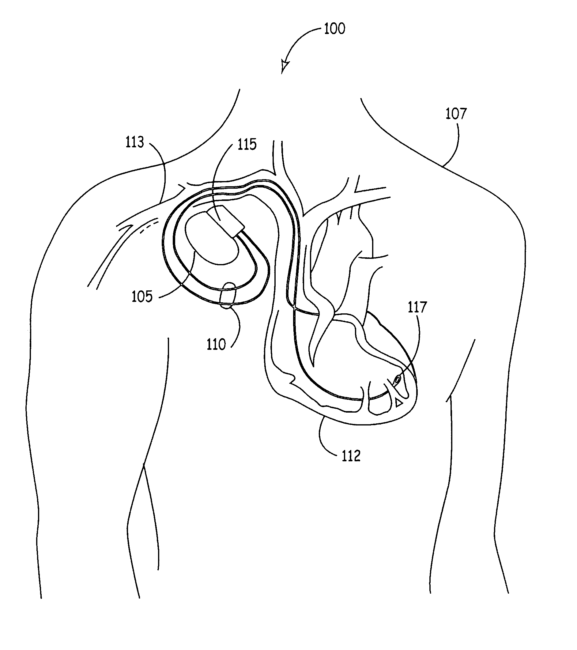
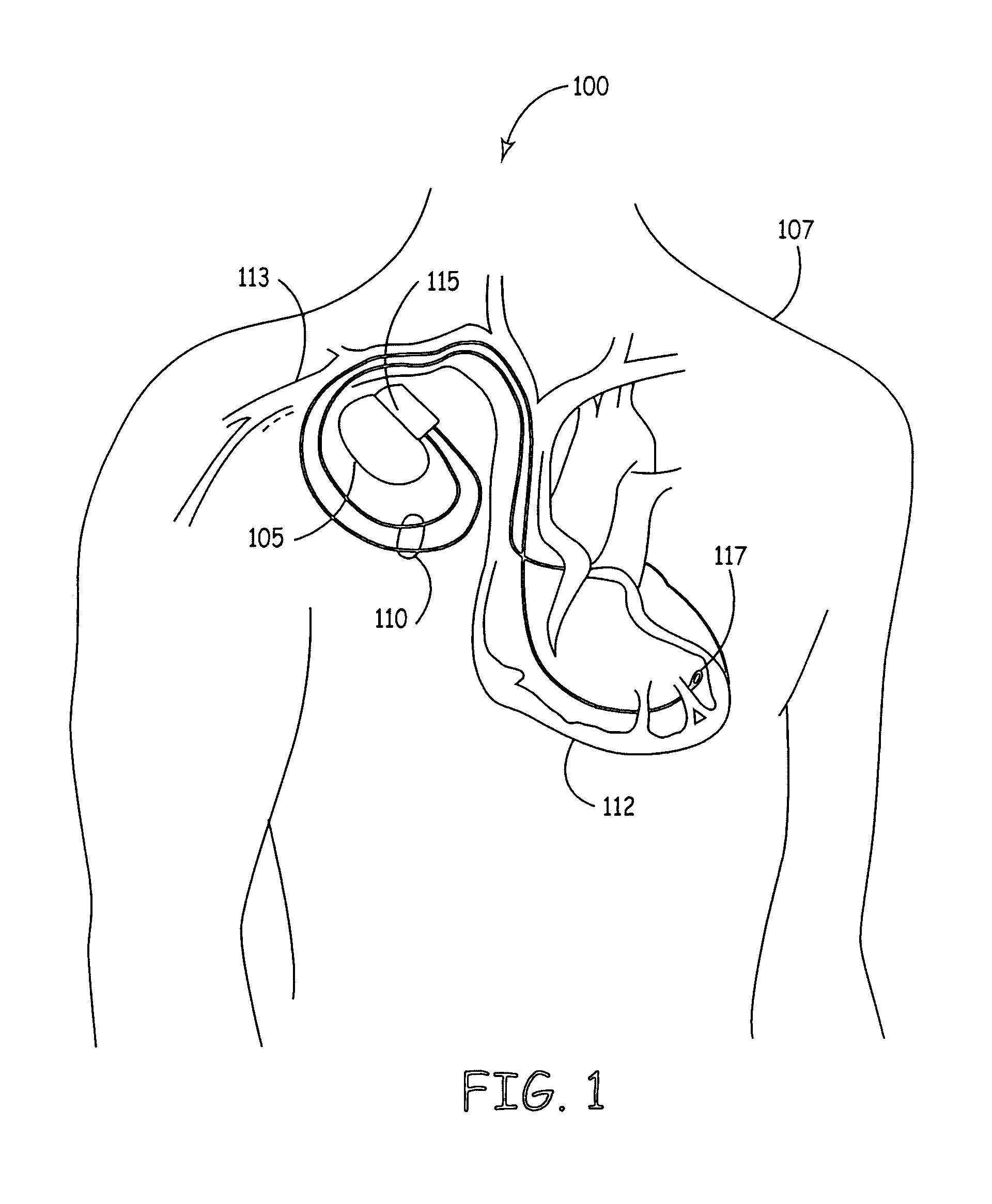
[0034] Turning now to the drawings, and specifically referring to FIG. 1, an IMD (IMD) system 100 is shown in accordance with one embodiment of the present invention. The IMD system 100 includes an IMD 105 that has been implanted in a patient 107. In accordance with the illustr...


PUM


Abstract

An implantable medical device (IMD) includes a detector for detecting the presence of x-ray radiation, where the presence of x-ray radiation is detected in response to the strength of the x-ray radiation exceeding a first threshold. In one embodiment, the IMD includes a processor for adjusting a cardiac stimulation rate IMD in response to determining that the strength of the detected x-ray radiation exceeds a second threshold. The second pre-selected x-ray radiation threshold is greater than the first pre-selected x-ray radiation threshold. In another embodiment, the implantable device includes a detector for detecting the presence of any amount x-ray radiation and a processor for adjusting a stimulation rate provided by the IMD in response to detected x-ray radiation to reduce the chance of over-sampling artifacts or inappropriate therapy delivery.

Description

CROSS REFERENCE TO RELATED APPLICATION [0001] The present patent document is related to co-pending non-provisional U.S. patent application Ser. No. ______, entitled, “METHODS AND APPARATUS FOR REDUCING DELETERIOUS EFFECTS OF X-RAY RADIATION UPON IMPLANTABLE MEDICAL DEVICE CIRCUITRY,” filed on even date herewith; the contents of which are hereby incorporated by reference.FIELD OF THE INVENTION [0002] This invention relates generally to implantable medical devices (IMDs) and, more particularly, to a method and apparatus for controlling an active IMDs (e.g., pacemakers, nerve stimulators, therapeutic-substance pumps, physiologic monitors, etc.) when exposed to x-ray radiation during for example positron emission tomography (PET), computed tomography (CT), fluoroscopy-type and other x-ray imaging scans including newer imaging modalities such as digital subtraction angiography (DSA) and Angio-CT as well an incident x-ray radiation of unknown source. DESCRIPTION OF THE RELATED ART [0003] ...

Claims


Application Information

Patent Timeline
Patent Type & Authority Applications(United States)
IPC IPC(8): A61B5/05
CPCA61B5/0428A61N1/3718A61N1/37A61N1/16A61B5/30A61B5/308
Inventor CLEMENT, WESLEY J.FUJIMOTO, HIROSHIWILKINSON, JEFFREY D.BUYSMAN, JOHN R.BORGERDING, GIRARD B.
Owner MEDTRONIC INC
Why Eureka
Try Eureka