
Filter element and filter system

a filter element and filter system technology, applied in the field of filter element and filter system, can solve the problems of insufficient filtering of granular adsorbents through the activated carbon fiber layer, inability to ensure that a space which is to be protected from air loaded with pollutants is contaminated as little as possible, and filter elements known from the related art have significant disadvantages in regard to efficiency and effective utilization of load capacity, and achieve optimal utilization of load capacity of the filter element used

Inactive Publication Date: 2006-10-12
CARL FREUDENBERG KG
View PDF5 Cites 28 Cited by
  • Summary
  • Abstract
  • Description
  • Claims
  • Application Information

AI Technical Summary

Benefits of technology

[0007] It was first recognized according to the present invention that the filter elements of the prior art have significant disadvantages. In a second step, it was then recognized that activated carbon fibers are characterized by high adsorption rates because of their dimensions. In a third step, it was then recognized that the system of the layers according to the present invention surprisingly makes it possible to achieve a high adsorption capacity. Furthermore, it was recognized that the system according to the present invention causes a smaller proportion of air loaded with pollutants to pass through the first layer unfiltered. Finally, it was recognized that the system according to the present invention causes a higher adsorption rate of the overall system. A combinatorial effect is thus implemented by the system according to the present invention, which is expressed in the increase of the adsorption capacity and the adsorption rate with optimum utilization of the load capacity of the filter element. The object thus may be achieved.
[0019] The filter element may have layers which include areas of different material concentrations. In particular, it is conceivable for this purpose that gradients in regard to specific material concentrations are implemented within a layer. This construction allows the increase of the absorption capacity in the downstream direction, for example, if the adsorbent concentration in the downstream direction increases.

Problems solved by technology

It is a disadvantage in this case that the granular adsorbents frequently have not yet reached their maximum load of adsorbate and nonetheless a majority of the pollutants flow past them.
In particular, the problem results that adsorptives which could have been absorbed by the capacity of the granular adsorbents also pass through the activated carbon fiber layer insufficiently filtered.
Because of this behavior of the filter elements forming the species, it cannot be ensured that a space which is to be protected from air loaded with pollutants is contaminated as little as possible.
The filter elements known from the related art thus have significant disadvantages in regard to their efficiency and effective utilization of their load capability.

Method used


Image

  • Filter element and filter system
  • Filter element and filter system
  • Filter element and filter system

Examples


Embodiment Construction

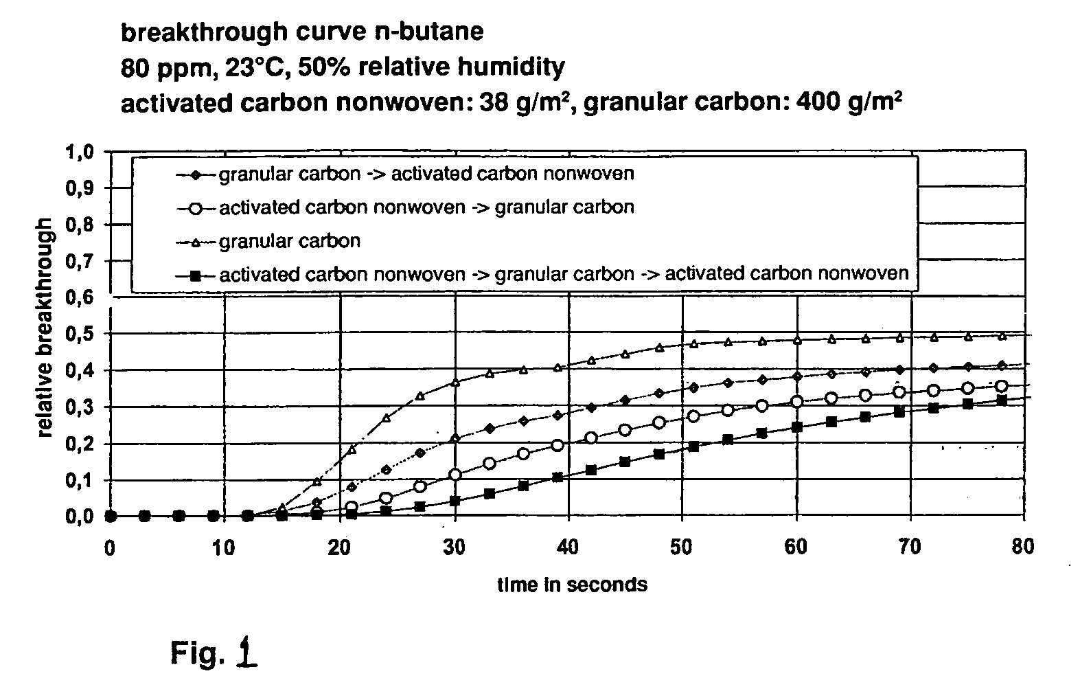
[0026]FIG. 1 shows a diagram in which the breakthrough behavior of four filter elements is shown, two of the filter elements being in accordance with the present invention and two beign for comparison purposes.

[0027] The curve identified using squares shows the behavior of a filter element having a sandwich-type construction according to the present invention. This includes a first layer made of an activated carbon fiber nonwoven having 38 g / m2 mass per unit area, a second layer of granular activated carbon having 400 g / m2 mass per unit area, and a third layer which is identical to the first layer. The activated carbon fiber nonwoven is thus on the inflow side, and the second layer adjoins this layer in the direction of the outflow.

[0028] Furthermore, the curve identified using circles shows a filter element according to the present invention in which an activated carbon fiber layer and having a mass per unit area of 38 g / m2 is situated on the inflow side. This is followed by a la...


PUM

PropertyMeasurementUnit
Diameteraaaaaaaaaa
Sizeaaaaaaaaaa
Sizeaaaaaaaaaa

Abstract

A filter element, including a filter body having an inflow side and outflow side, the filter body being constructed in layers, at least one layer including granular adsorbents and at least one further layer including activated carbon fibers. The filter element may be used in a filter system which ensures optimum utilization of the load capacity of the filter element used in that a first layer, which includes activated carbon fibers is assigned to the inflow side and a second layer, which includes granular adsorbents, adjoins this layer on the outflow side. A filter system includes the filter element.

Description

[0001] This claims the benefit of German Patent Application No. 10 2005 016 677.6 filed Apr. 12, 2005 and hereby incorporated by reference herein. [0002] The present invention relates to a filter element, including a filter body having an inflow side and an outflow side, the filter body being constructed in layers, at least one layer including granular adsorbents and at least one further layer including activated carbon fibers. Furthermore, the present invention relates to a filter system. BACKGROUND [0003] Filter elements of this type, which combine granular adsorbents and planar formations made of activated carbon fibers, are known. The granular adsorbents are situated in this case upstream from the planar formations made of activated carbon fibers. Situating the granular adsorbents upstream from the activated carbon fiber layer should cause a particularly favorable absorption of pollutants contained in the air. Part of the pollutants contained in the air—the adsorptives—is absorb...

Claims


Application Information

Patent Timeline
IPC IPC(8): B01D53/02
CPCB01D53/0407B01D2253/102B01D2259/4146B01D2253/304B01D2253/306B01D2253/108B01D39/00
Inventor BRAEUNLING, VOLKERSCHMITT, DANIELBADER, ROBERT
Owner CARL FREUDENBERG KG
Learn More