Method for the production of monocrystalline structures and component

a monocrystalline structure and monocrystalline technology, applied in the direction of single crystal growth, polycrystalline material growth, condensed vapor growth, etc., can solve the problems of misalignment of applied materials, lack of mechanical properties in this region, adverse effect on the mechanical load-bearing capacity of the component as a whole, etc., to prevent recrystallization and creep in the crystal structure, the effect of reducing internal stresses

Inactive Publication Date: 2006-10-12
SIEMENS AG
View PDF57 Cites 7 Cited by
  • Summary
  • Abstract
  • Description
  • Claims
  • Application Information

AI Technical Summary

Benefits of technology

[0019] The process for building up single crystals from the same material approximately the same material or also materials that differ from the substrate makes it possible, for example, to reconstruct or supplement workpieces which have single-crystal structures and have been damaged or have become worn. By way of example, nowadays there are rotor blades of gas turbines which consist of single crystals of what are known as metal superalloys and which can be repaired by the process if they have been damaged.
[0026] If the substrate is brought to a preheating temperature in the range from 600° C. to 1100° C. by blind tracking, i.e. without the supply of material, using the laser or induction means, and this temperature is maintained for example while the material is being built up, the stresses in the substrate and in the built-up single crystal, but also between the substrate and the crystalline structure which has been built up epitaxially thereon, are reduced, which contributes to preventing recrystallization and creep in the crystal structure.
[0027] Stress-relief annealing of substrate and the single crystal layer which has been rebuilt for about 1 hour at a temperature in the range from approximately 1000° C. to 1250° C., for CMSX-4 at approx. 1150° C., followed by slow cooling, reduces internal stresses, which could destroy the single-crystal structures through recrystallization and creep. However, the stress-relief annealing could also take place immediately after the application of the epitaxial layer using an RF device.

Problems solved by technology

This often leads to misalignments, since structures which are not in single crystal form, representing misalignments, are present in the vicinity of the surface immediately after production and use.
The structure of the material to be applied, however, is oriented on the basis of the structure of the surface to which it is applied, so that misalignments also occur in the applied material.
Consequently, the mechanical properties in this region are lacking, which has an adverse effect on the mechanical load-bearing capacity of the component as a whole.

Method used


Image

  • Method for the production of monocrystalline structures and component
  • Method for the production of monocrystalline structures and component

Examples


Embodiment Construction

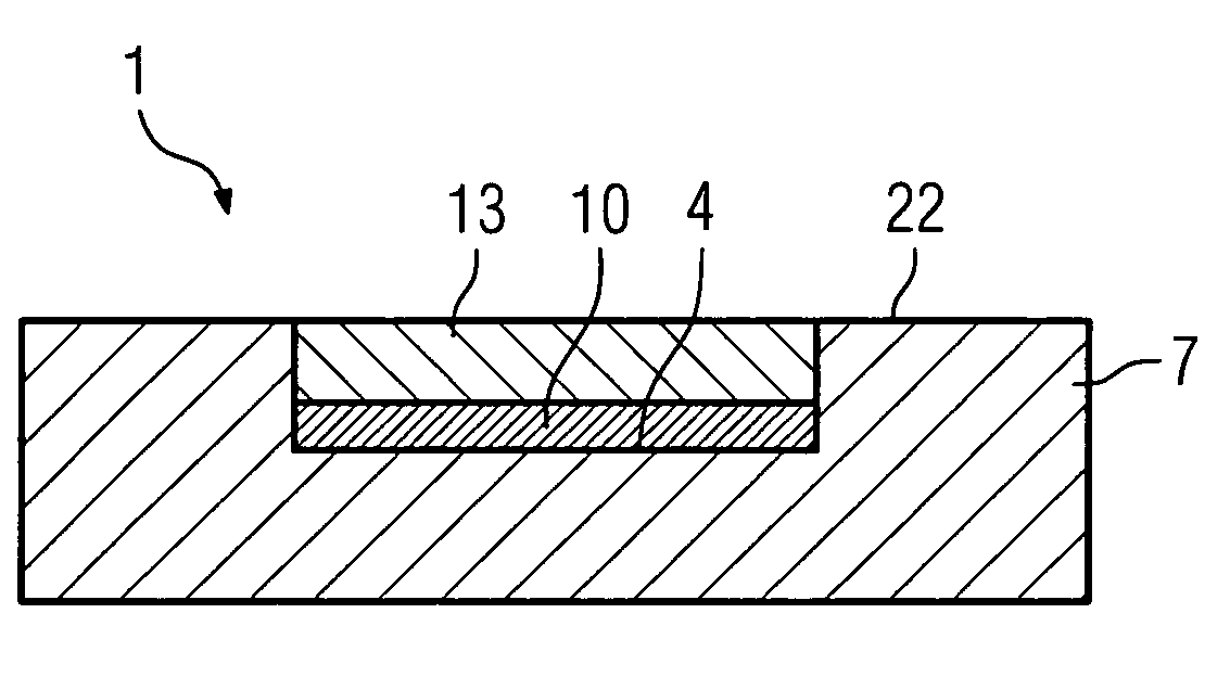
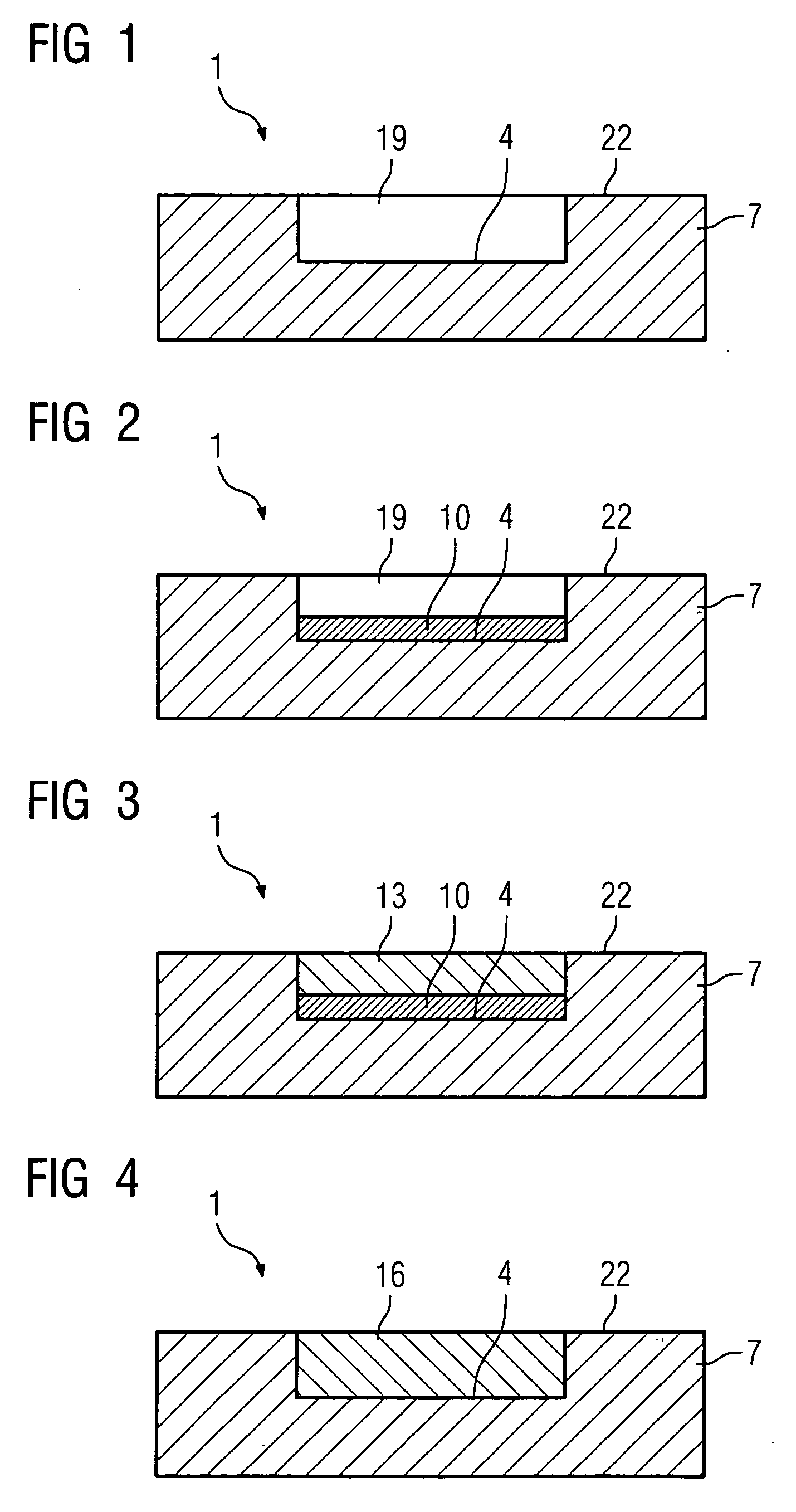
[0032]FIG. 1 shows a component 1, in particular a component for a gas turbine, such as for example a turbine blade or vane, which comprises a substrate 7.

[0033] The substrate 7 is in particular a nickel-based or cobalt-based metallic superalloy and in particular has a single-crystal structure.

[0034] New material, which is to have a single-crystal structure similar to or exactly the same as that of the substrate 7, is to be introduced either on the surface 22 of the component or in a recess 19 in the component 1.

[0035] The recess 19 is, for example, a location on the component 1 at which material has been removed on account of the presence of corrosion and / or cracks. These degraded regions were removed without leaving any residues and need to be refilled, the aim being for them to have the same mechanical properties as the substrate 7.

[0036]FIG. 2 shows the component 1 in a further process step. According to the invention, an intermediate layer 10 is applied to the base surface 4...


PUM

PropertyMeasurementUnit
temperatureaaaaaaaaaa
structuresaaaaaaaaaa

Abstract

According to prior art, structural errors in substrates in epitactic crystal growth are often carried over from the substrate on which the new material is to be deposited. This leads to a reduction in mechanical properties. According to the method, an intermediate layer is deposited prior to the deposition of epitactic material. Said intermediate layer prevents structural errors in the substrate from being carried over to the newly filled area.

Description

CROSS REFERENCE To RELATED APPLICATIONS [0001] This application is the US National Stage of International Application No. PCT / EP2003 / 014255, filed Dec. 15, 2003 and claims the benefit thereof. The International Application claims the benefits of European application No. 03000446.9 EP filed Jan. 10, 2003, all of the applications are incorporated by reference herein in their entirety.FIELD OF INVENTION [0002] The invention relates to a process for producing single-crystal structures, in particular from superalloys, in accordance with the preamble of the independent claims. BACKGROUND OF INVENTION [0003] Metallic workpieces with a single-crystal structure or directionally solidified structures are used as components of machines which, in operation, are subject to high mechanical, thermal and / or chemical loads. By way of example, blades and vanes of gas turbines, in particular including rotor blades for aircraft engines, but also those used in stationary gas turbines, are produced from ...

Claims


Application Information

Patent Timeline
Patent Type & Authority Applications(United States)
IPC IPC(8): C30B25/00C30B28/12C30B28/14C30B11/00C30B29/52
CPCC30B11/00C30B29/52
Inventor BOSTANJOGLO, GEORGKRUGER, URSUSSTEINBACH, JAN
Owner SIEMENS AG
Why Eureka
Try Eureka