Self-leveling in-situ device and method for passively removing oil from water wells

a technology of self-leveling and in-situ device, which is applied in the direction of separation process, chemistry apparatus and processes, and well accessories, etc., can solve the problems of a buffer device, and achieve the effect of easy fabrication and inexpensive way

Inactive Publication Date: 2006-10-12
UNION OIL OF CALIFORNIA
View PDF8 Cites 4 Cited by
  • Summary
  • Abstract
  • Description
  • Claims
  • Application Information

AI Technical Summary

Benefits of technology

[0005] In a preferred embodiment the buoyant device comprises a piece of plastic pipe or tube sealed at both ends with the hydrophobic sorbtive material wrapped around the tube. The device is lowered into the well and dropped into the liquids where it is self-leveling, i.e., where it either floats in the layer of non-aqueous liquids or in the water such that at least a portion of the hydrophobic sorbtive material is sitting in the floating layer of non-aqueous liquids. Because the device floats and is therefore self-leveling, it is not necessary to suspend or hang it into the well from outside the well while guessing where it should be positioned axially inside the well so it sits in the layer of non-aqueous liquids, whose level in the well is constantly changing with the level of the groundwater. Since the device is easy to fabricate from readily available materials and has no moving parts, its manufacture and use is an inexpensive way to comply with environmental regulations that require removing non-aqueous liquid pollutants from groundwater wells.

Problems solved by technology

However, if the layer of non-aqueous liquids is rather shallow or thin, the buoyant device will sink through the liquids and float in the water such that a portion of the buoyant device extends above the surface of the water and into the non-aqueous liquids.

Method used


Image

  • Self-leveling in-situ device and method for passively removing oil from water wells
  • Self-leveling in-situ device and method for passively removing oil from water wells

Examples


Embodiment Construction

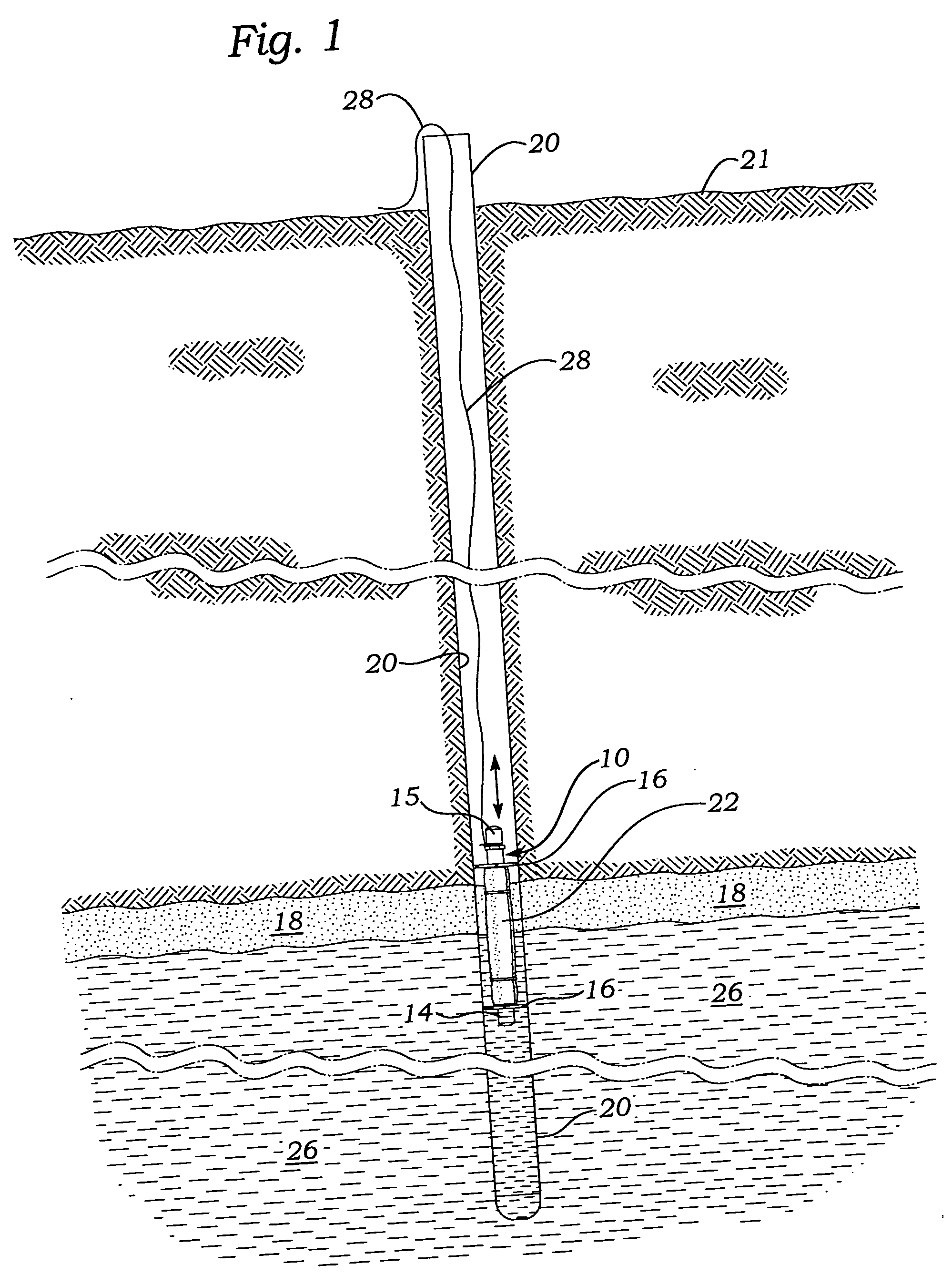
[0010]FIGS. 1-3 in the drawings illustrate one embodiment of the non-inflatable buoyant oil removal device 10 of the invention and its use for removing non-aqueous liquids 18, such as hydrocarbons, from a monitoring well 20, which extends from the ground surface 21 into the groundwater 26. The monitoring well may be fairly shallow extending into the ground between 20 and 30 feet or much deeper, for example, up to as much as about 100 feet. The layer of non-aqueous liquid 18 floating on the surface of the water can vary in thickness from less than about 1 inch to as much as 25 feet. Typically, the thickness of the layer of non-aqueous liquids ranges from about 0.01 to about 6 feet.

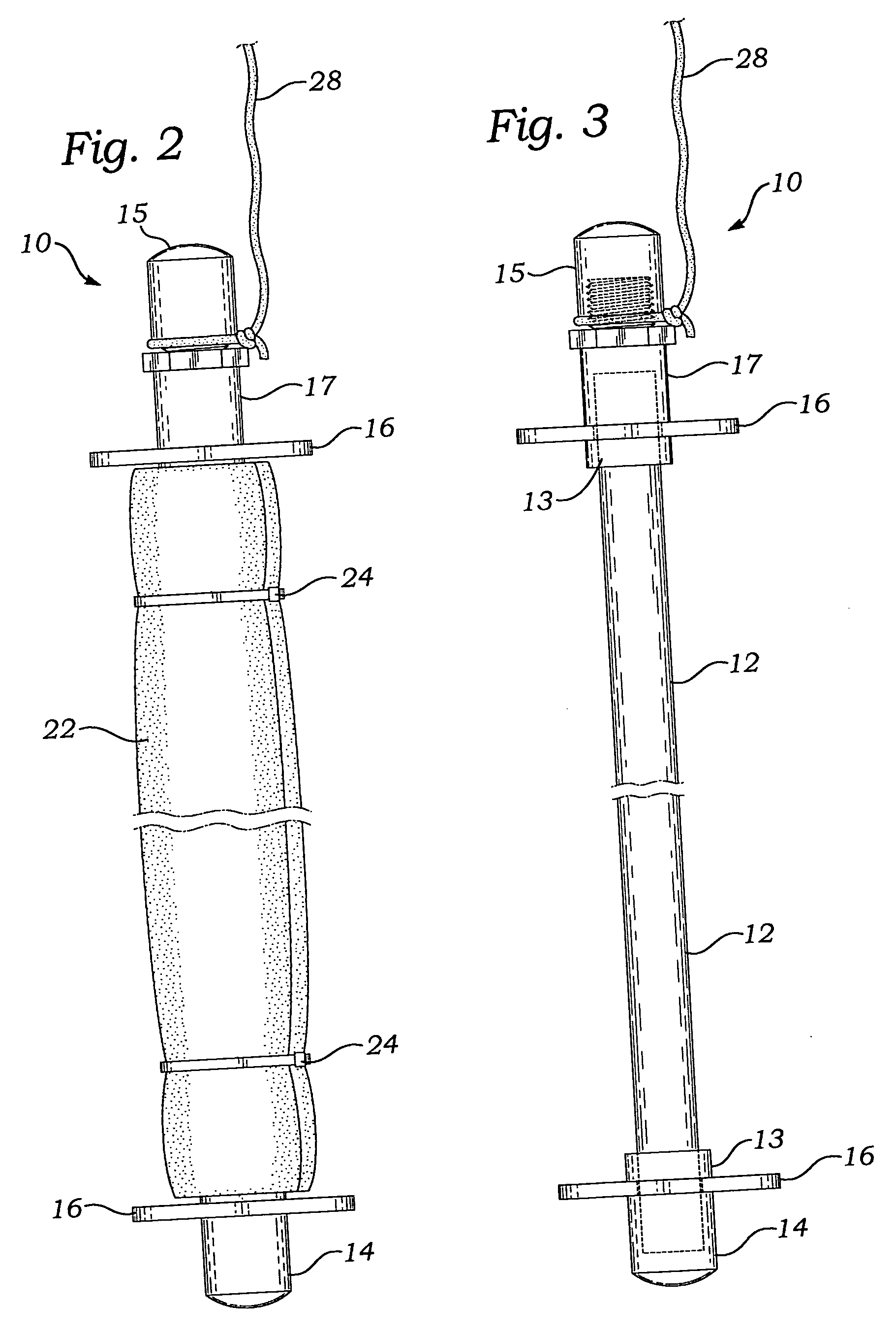
[0011] As seen in FIGS. 2 and 3, the oil removal device 10 comprises a hollow tube 12, upper and lower retaining rings 13, coupler 17, upper end cap 15, lower end cap 14, centralizers 16 and hydrophobic sorptive pad 22, which is wrapped around tube 12 and secured thereto with plastic or metal ties 24. A ba...


PUM

PropertyMeasurementUnit
diameteraaaaaaaaaa
diameteraaaaaaaaaa
diameteraaaaaaaaaa

Abstract

A simple and inexpensive device with no moving arts for removing from a well non-aqueous liquids, such as gasoline or crude oil, that accumulate on top of the water table in the well comprises a buoyant elongated member, such as a plastic tube sealed at both ends, and a hydrophobic sorbtive material preferably attached to the outside of the tube. The buoyant device is lowered into the well where it floats either in the non-aqueous liquids or in the water such that the sorbtive material is in contact with and absorbs the non-aqueous liquids from the surface of the water. The buoyant device is then removed from the well, the spent sorbtive material replaced with fresh sorbtive material and the device again lowered into the well for further removal of non-aqueous liquids.

Description

BACKGROUND OF INVENTION [0001] This invention relates to a device and method for removing from a well light non-aqueous liquids that float on the surface of water in the well, and is particularly concerned with a simple inexpensive device having no moving parts that can passively remove crude oil and other hydrocarbons from groundwater wells. [0002] It is not uncommon for light hydrocarbons, such as crude oil, gasoline and other distillate products, to escape into the environment from oil producing fields, service stations, refineries, natural gas processing plants and other related petroleum processing facilities. Quite frequently these light hydrocarbons work themselves into the soil where they migrate downwardly and end up collecting on the surface of the water table. These hydrocarbons float on the water surface, spread across the water in the direction of least resistance and partially dissolve into the water causing significant pollution. Thus, most state and local governments...

Claims


Application Information

Patent Timeline
Patent Type & Authority Applications(United States)
IPC IPC(8): E21B43/00C02F1/28
CPCE03B3/15C02F1/681
Inventor THORSELL, G. SCOTT
Owner UNION OIL OF CALIFORNIA
Why Eureka
Try Eureka