Cooling apparatus for electronic device

a technology for electronic devices and cooling components, applied in the field of cooling, can solve the problems of increasing the external dimensions and weight of the electronic device, affecting and deteriorating local heat conduction, etc., and achieves the effect of thin and light weight, enhancing the performance of the cooling apparatus

Inactive Publication Date: 2006-10-12
HITACHI LTD
View PDF30 Cites 11 Cited by
  • Summary
  • Abstract
  • Description
  • Claims
  • Application Information

AI Technical Summary

Benefits of technology

[0009] With the configuration according to the present invention, the heat may be sufficiently diffused in the housing, and accordingly, the heat is conducted with a uniform heat flux at a surface made into contact with a cooling component, thereby enhancing the performance of the cooling apparatus as well as making the housing thin and light-weight.

Problems solved by technology

On the contrary, should the micro-package be small-sized, the density of heat conducted to the housing would be further increased, resulting in insufficient heat distribution in the housing made of a conventionally used material such as copper or aluminum, and the heat is conducted with a convexity pattern between contact surfaces of the housing and the cooling component, that is, the heat conduction is largest at its center part but is decreased toward its periphery, and accordingly, there has been caused such a disadvantage that the heat conduction is locally deteriorated, and the cooling component connected to the housing cannot satisfactorily exhibit its function.
However, this method has caused a disadvantage that the external dimensions and weight of the electronic device are increased due to great increase in the thickness of the housing.

Method used


Image

  • Cooling apparatus for electronic device
  • Cooling apparatus for electronic device
  • Cooling apparatus for electronic device

Examples


embodiment 2

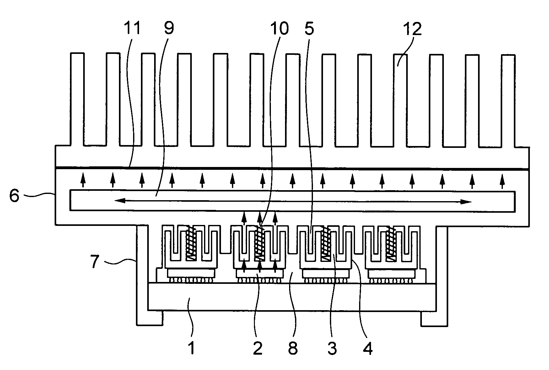
[0021]FIG. 2 is a sectional view illustrating an embodiment 2 according to the present invention. In FIG. 2, a heat pipe 13 is embedded in a recess formed in an upper part of a housing 16. Contact surfaces of the housing 16 and the heat pipe 13 are formed by pressing them against each other, directly, or through the intermediary of a thermal conductive medium such as thermal conductive grease. Except that stated just above, the configuration of the embodiment2 is the same as that shown in FIG. 1.

embodiment 1

[0022] According to this embodiment, there may be exhibited technical effects and advantages the same as those obtained by the embodiment 1.

[0023] It is noted that the heat-pipe 13 may be composed of one or more of rod-like or plane heat-pipes which are embedded.

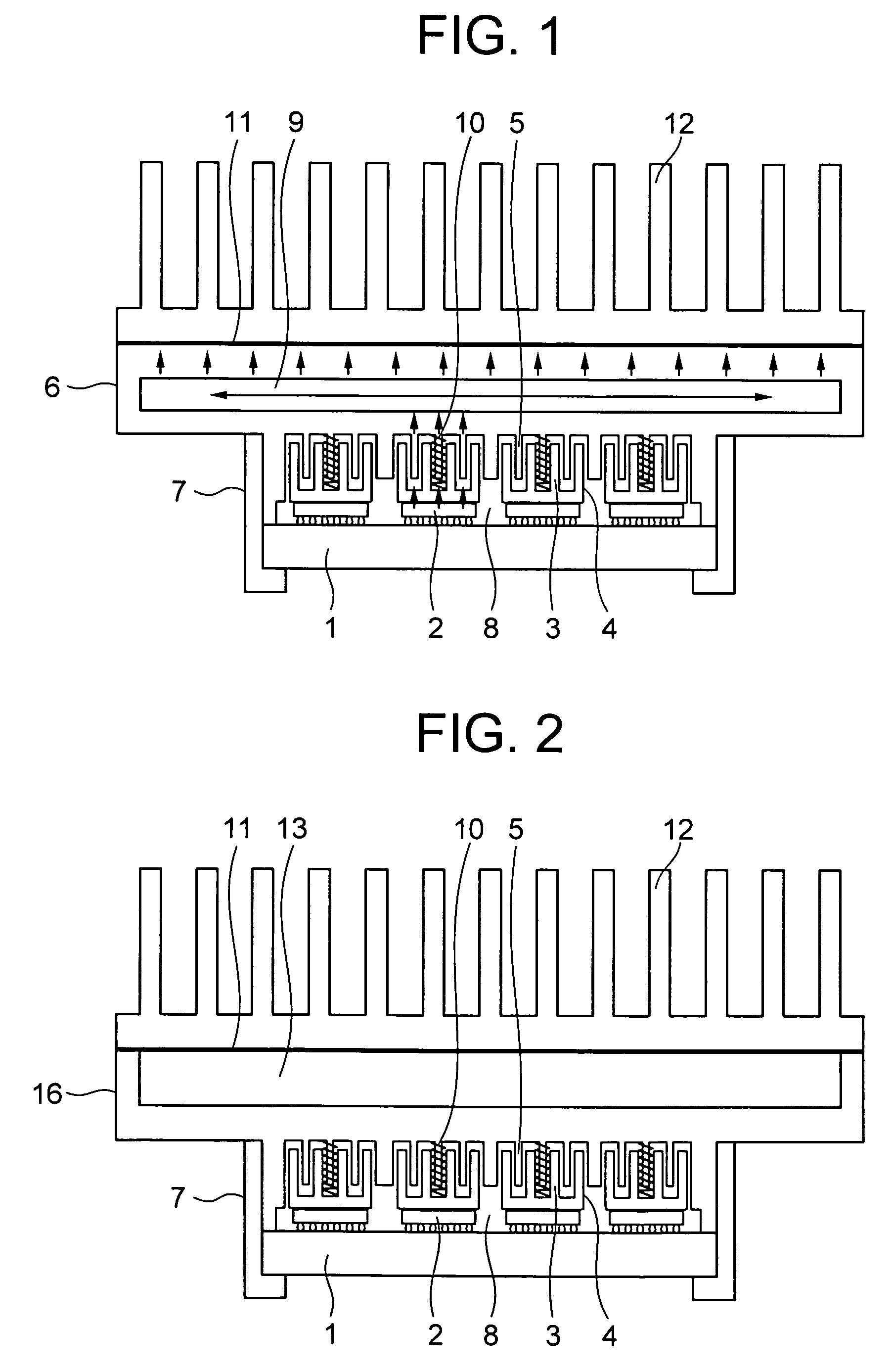
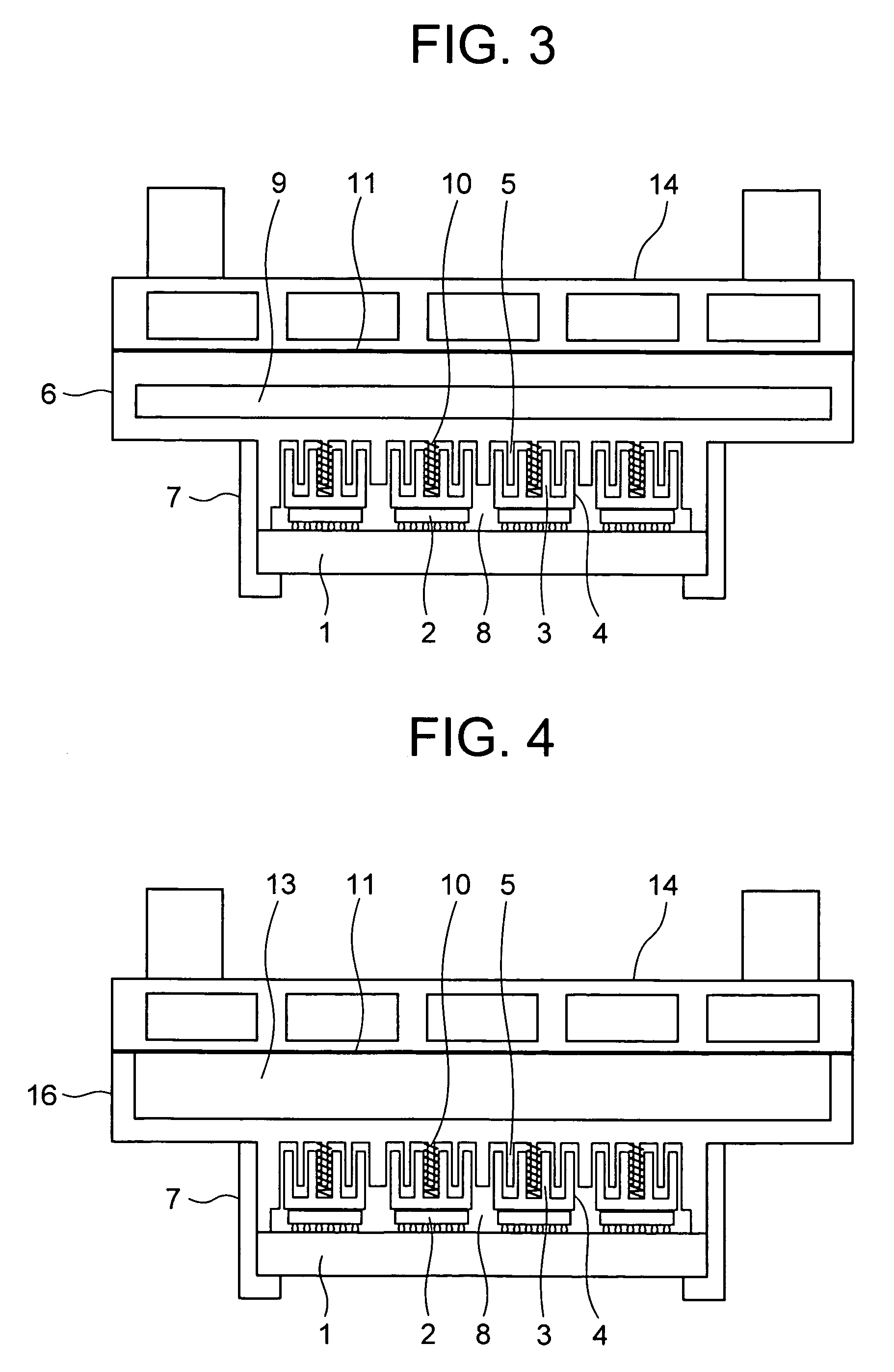
[0024]FIG. 3 is a sectional view illustrating an embodiment 3 according to the present invention. In FIG. 3, a cooling water jacket 14 is mounted on the housing 6 through the intermediary of a flexible thermal conductive medium 11 such as thermal conductive grease. Cooling water at a low temperature flows through the water cooling jacket 14. The configuration of the embodiment 3 is the same as that shown in FIG. 1, except that stated just above.

[0025] With the configuration stated above, the heat conducted to the plane heat pipe 9, similar to the plane heat pipe 9 shown in FIG. 1, is distributed in the housing 6 by means of the plane heat pipe 9, and then, the thus distributed heat is uniformly transmitted to the cooling w...

embodiment 4

[0027]FIG. 4 is a sectional view illustrating an embodiment 4 according to the present invention. In FIG. 4, a heat pipe 13 is embedded in the outer surface of a housing 16. A thermal conductive medium 8 such as grease may be interposed between contact surfaces of the housing 16 and the heat pipe 13. Alternatively, the surfaces of the housing 16 and the heat pipe 13 may be made into press-contact with each other. It is noted that the configuration of this embodiment is the same as that shown in FIG. 3, except that as stated just above.


PUM


Abstract

A cooling apparatus for cooling a plurality of electronic devices each having a large heating value and a small area, capable of effectively cooling the semiconductor chips with the use of a single cooler, comprises a plurality of thermal conductors mounted on the electronic devices and formed with thermal conductive fins, a housing formed with fins fitted with the fins of the thermal conductors, and a cooling device mounted on the housing, for removing heat from the electronic devices, wherein the housing is formed therein with a plane heat-pipe.

Description

INCORPORATION BY REFERENCE [0001] The present application claims priority from Japanese application JP 2005-059852 filed on Mar. 4, 2005, the content of which is hereby incorporated by reference into this application. FIELD OF THE INVENTION [0002] The present invention relates to a cooling. apparatus for removing heat generated from an electronic device such as a semiconductor chip or an integrated circuit chip. DESCRIPTION OF THE RELATED ART [0003] There has been increased demands for speeding up a process in an electronic computer, and accordingly, these years, circuit chips in which semiconductor devices are integrated in a large scale have been developed. Further, in order to shorten electric wirings connecting among these integrated circuit chips as possible as it can, there have been developed methods for mounting a plurality of integrated circuit chips in a micro-package. [0004] Conventionally, in particular, with respect to a large scale electronic computer, a cooling appara...

Claims


Application Information

Patent Timeline
Patent Type & Authority Applications(United States)
IPC IPC(8): H05K7/20
CPCH01L23/427H01L23/4338H01L2224/73253H01L2224/16H01L2924/12044H01L2924/00014H01L2924/00011H01L2224/0401
Inventor ENAMI, TAKAFUMIIDEI, AKIOSATO, SHIGEMASANINOMIYA, CHIKAKAZU
Owner HITACHI LTD
Why Eureka
Try Eureka