Closed pressure-keeping system for liquid hydrogen storage

a technology of liquid hydrogen storage and pressure-keeping system, which is applied in the direction of non-pressure vessels, containers discharging from pressure vessels, containers discharging from non-pressure vessels, etc., can solve the problems of high cost, complicated cryo-valves that include the return device, and significant increase in the system pressure of storage vessels, so as to reduce the storage pressure

Inactive Publication Date: 2006-10-19
GM GLOBAL TECH OPERATIONS LLC
View PDF11 Cites 10 Cited by
  • Summary
  • Abstract
  • Description
  • Claims
  • Application Information

AI Technical Summary

Benefits of technology

[0013] In yet another feature, the pressure maintaining system further includes a safety valve that is in fluid communication with the gas phase hydrogen feed. The safety valve is operable to reduce a storage pressure when the storage pressure exceeds a tank threshold.

Problems solved by technology

However, reintroduction of gaseous hydrogen into the storage vessel can significantly increase the system pressure of the storage vessel.
Cryo-valves that include the return device are complicated and expensive.

Method used


Image

  • Closed pressure-keeping system for liquid hydrogen storage
  • Closed pressure-keeping system for liquid hydrogen storage
  • Closed pressure-keeping system for liquid hydrogen storage

Examples


Embodiment Construction

[0019] The following description of the preferred embodiments is merely exemplary in nature and is in no way intended to limit the invention, its application, or uses.

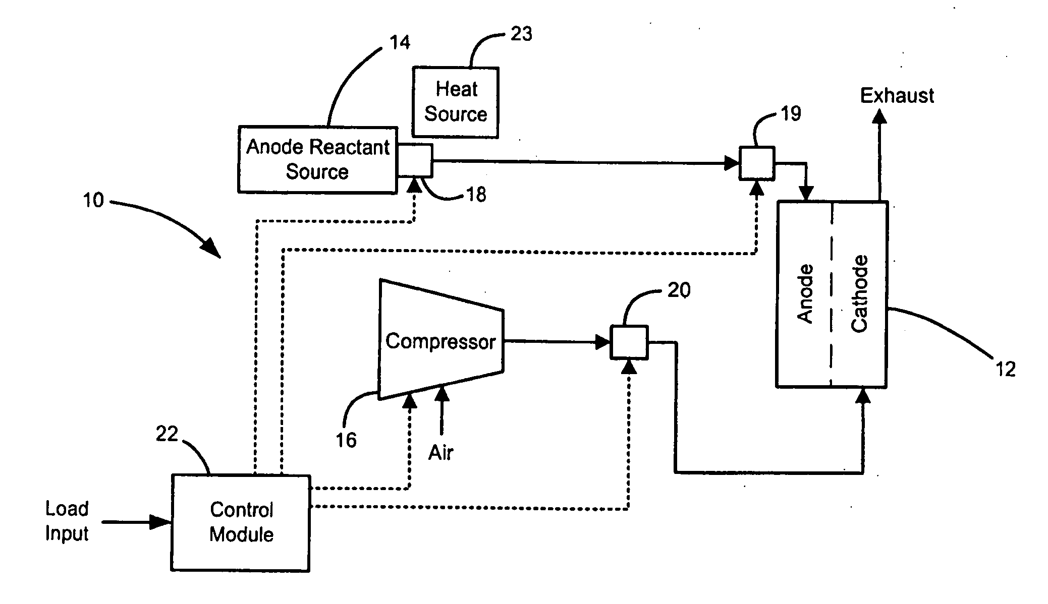
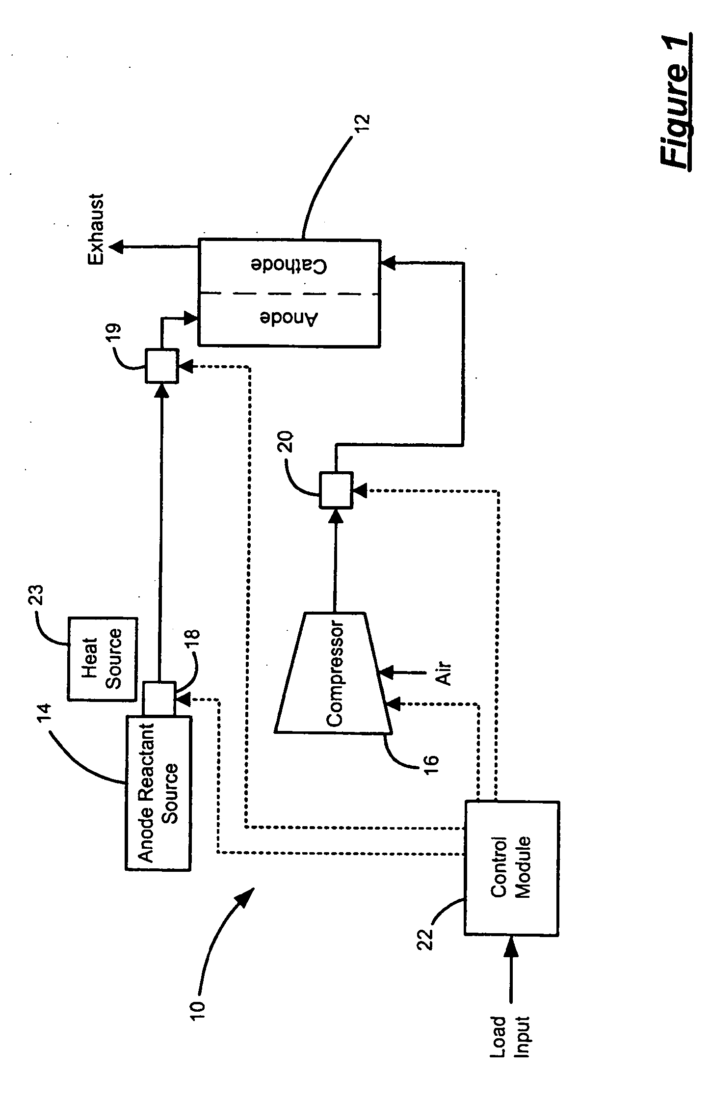
[0020] Referring now to FIG. 1, an exemplary fuel cell system 10 is illustrated. The fuel cell system 10 includes a fuel cell stack 12, a hydrogen storage system 14 and a compressor 16. The fuel cell system 10 further includes a pressure maintaining system 18 and a pressure management system 19. The pressure maintaining system 18 regulates the pressure within the hydrogen storage system 14 and operates independent of the fuel cell stack 12 (i.e., regardless of whether the fuel cell stack is ON or OFF), as discussed in further detail below. The pressure management system 19 regulates the pressure of the hydrogen provided to the fuel cell stack 12 and operates when the fuel cell stack 12 is ON.

[0021] The compressor 16 provides pressurized, oxygen-rich air to a cathode side of the fuel cell stack 12 through a regulator ...


PUM

PropertyMeasurementUnit
pressureaaaaaaaaaa
pressureaaaaaaaaaa
threshold storage pressureaaaaaaaaaa

Abstract

A pressure maintaining system for a hydrogen storage system includes a hydrogen supply feed that enables a hydrogen flow from the hydrogen storage system. A liquid phase hydrogen feed enables a liquid phase hydrogen flow to the hydrogen supply feed. A gas phase hydrogen feed enables a gas phase hydrogen flow to the hydrogen supply feed. A check valve enables fluid communication from the hydrogen supply feed to the liquid phase hydrogen feed when a pressure within the hydrogen supply feed is greater than a threshold pressure.

Description

FIELD OF THE INVENTION [0001] The present invention relates to hydrogen storage, and more particularly to a pressure maintaining system for hydrogen storage. BACKGROUND OF THE INVENTION [0002] Fuel cell systems are increasingly used as a power source in a wide variety of applications. Fuel cell propulsion systems have also been proposed for use in vehicles as a replacement for internal combustion engines. The fuel cells generate electricity that is used to charge batteries and / or to power an electric motor. A solid-polymer-electrolyte fuel cell includes a membrane that is sandwiched between an anode and a cathode. To produce electricity through an electrochemical reaction, a fuel, commonly hydrogen (H2), but also either methane (CH4) or methanol (CH3OH), is supplied to the anode and an oxidant, such as oxygen (O2) is supplied to the cathode. The source of the oxygen is commonly air. [0003] In a first half-cell reaction, dissociation of the hydrogen (H2) at the anode generates hydrog...

Claims


Application Information

Patent Timeline
Patent Type & Authority Applications(United States)
IPC IPC(8): F17B1/00
CPCF17C5/06Y02T90/32F17C9/02F17C13/025F17C2221/012F17C2223/0161F17C2223/033F17C2223/035F17C2223/043F17C2223/047F17C2225/0123F17C2225/033F17C2225/035F17C2227/0304F17C2227/0309F17C2227/0388F17C2250/032F17C2250/043F17C2250/0626F17C2260/035F17C2265/025F17C2265/031F17C2265/066F17C2270/0184H01M8/04201H01M8/04208H01M2008/1095H01M2250/20Y02E60/321Y02E60/34Y02E60/50F17C7/04Y02P90/45Y02E60/32Y02T90/40
Inventor MATOS DA SILVA, JADERLINDNER, MARKUSIMMEL, RAINER
Owner GM GLOBAL TECH OPERATIONS LLC
Why Eureka
Try Eureka