[0009] The new composite panel, as shown in FIGS. 1, and 4, provides enhanced, commonly used structural load-bearing sandwich wall-panel consisting of inner and outer concrete layers, interconnected by at least two longitudinal steel-sheet strips galvanized against corrosion. The gap between two concrete layers is partially filled with a layer of thermo-insulation of arbitrary depth. The rest of the gap remains empty being used for air circulation. The main feature achieved, besides well known properties of the structural sandwich, is a depth-adaptability which is available without considerable spending of material. Increasing the space between two concrete layers significantly enlarges moment of inertia of the cross-section of the panel whereby it is done by increasing the height of the steel web-strips that is almost negligible increase of material spend. What is really increased is the width of the air space between two concrete layers which cost nothing. Hence, the wall-panel, deriving its strength from lessening its slenderness (as its moment of inertia increases), becomes stronger by getting its concrete layers more apart, it is a small price to be paid to obtain a strong panel. The most commonly used steel trusses connecting the two concrete layers are hereby replaced by the steel strip webs which suit much better the purpose of constructing heavy buildings for several reasons: Firstly, steel strips are substantially stiffer than trusses. Steel webs, having considerable cross-section area, being strongly anchored to both the concrete layers can contribute in bearing some amount vertical load. Vertical load applied to the steel tube at the support is partially transmitted to the surrounding concrete to which the tube is anchored and partially along the two long continuous joining lines between the both concrete layers and the steel web, as shown in FIGS. 4, and 6, so that stress concentrations at supports are avoided. The amount of steel, spend for applied webs (containing no flanges) is approximately equal to the amount needed for trusses. Generally, more truss pieces then steel webs are needed to obtain the adequate stiffness of the panel which has to be stiff enough to resist lateral deflections within permitted limits. The applied arrangement of two steel mesh layers embedded within each concrete layer greatly increases its local stiffness, lessening simultaneously their possibilities to bend and crack. The short steel rod anchors inserted through holes in loops which are welded at both longitudinal edges of webs, serve primarily as anchors against slippage between concrete and web, keeping also the constant distance (equal to the short steel rod diameter) between two meshes along the concrete layer, as shown in FIG. 1. The reinforcement cage formed upon the mould, prior to concreting each concrete layer is well fixed, easy to place and control, with reliable interspaces what lessens tolerances. It is needed here to emphasize that introducing two steel wire meshes with additional longitudinal reinforcement or prestressing strands between them certainly enables use of less deep thin walls of different concrete elements than usually permitted by codes. However, codes, usually limiting concrete covers of beams and columns do not consider such cases when reinforcement is confined so optimally between two layer meshes.
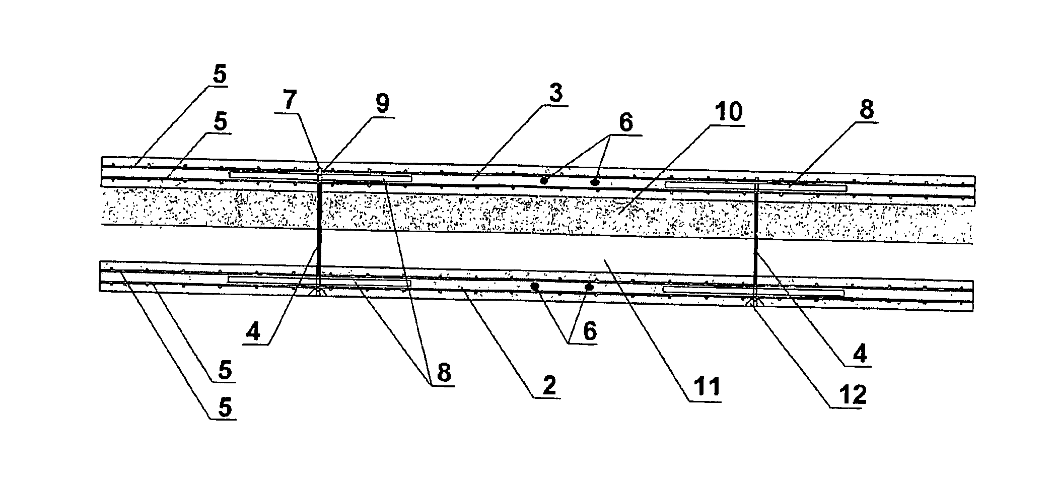
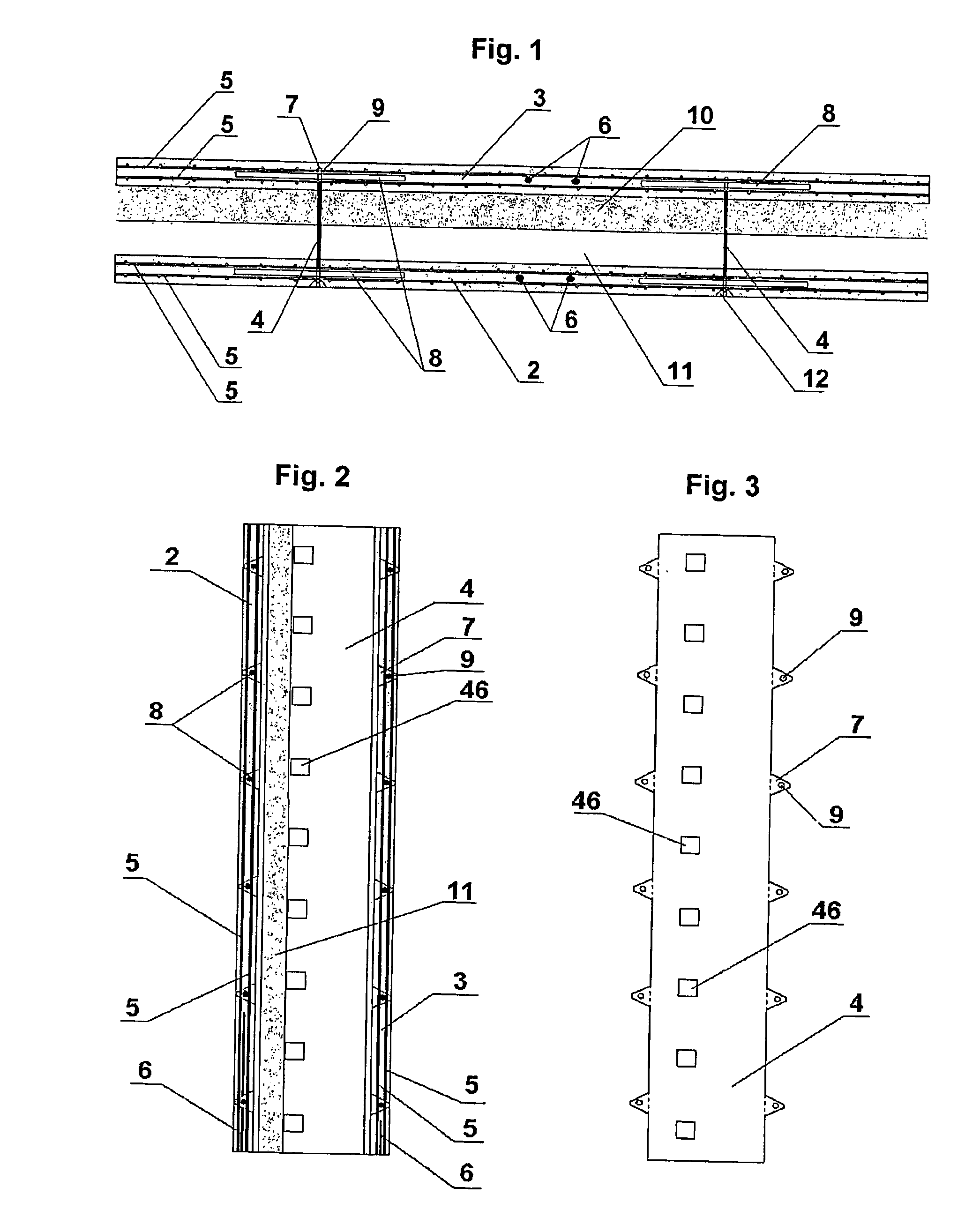
[0010] Another feature of the panel is introduced steel tube, perpendicularly positioned and welded to steel webs between two concrete layers, defining the top of supports for bearing roof or floor construction of assembled units, allowing no eccentricity to occur. Reactions of supported roofs or floors units are thereby applied centrically to the steel tube which is anchored to both concrete layers at the top of the support. The steel tube is hence welded to both steel webs so that reactions are efficiently transmitted to both concrete layers avoiding in that way stress concentrations near supports. The new panel is initially (during 
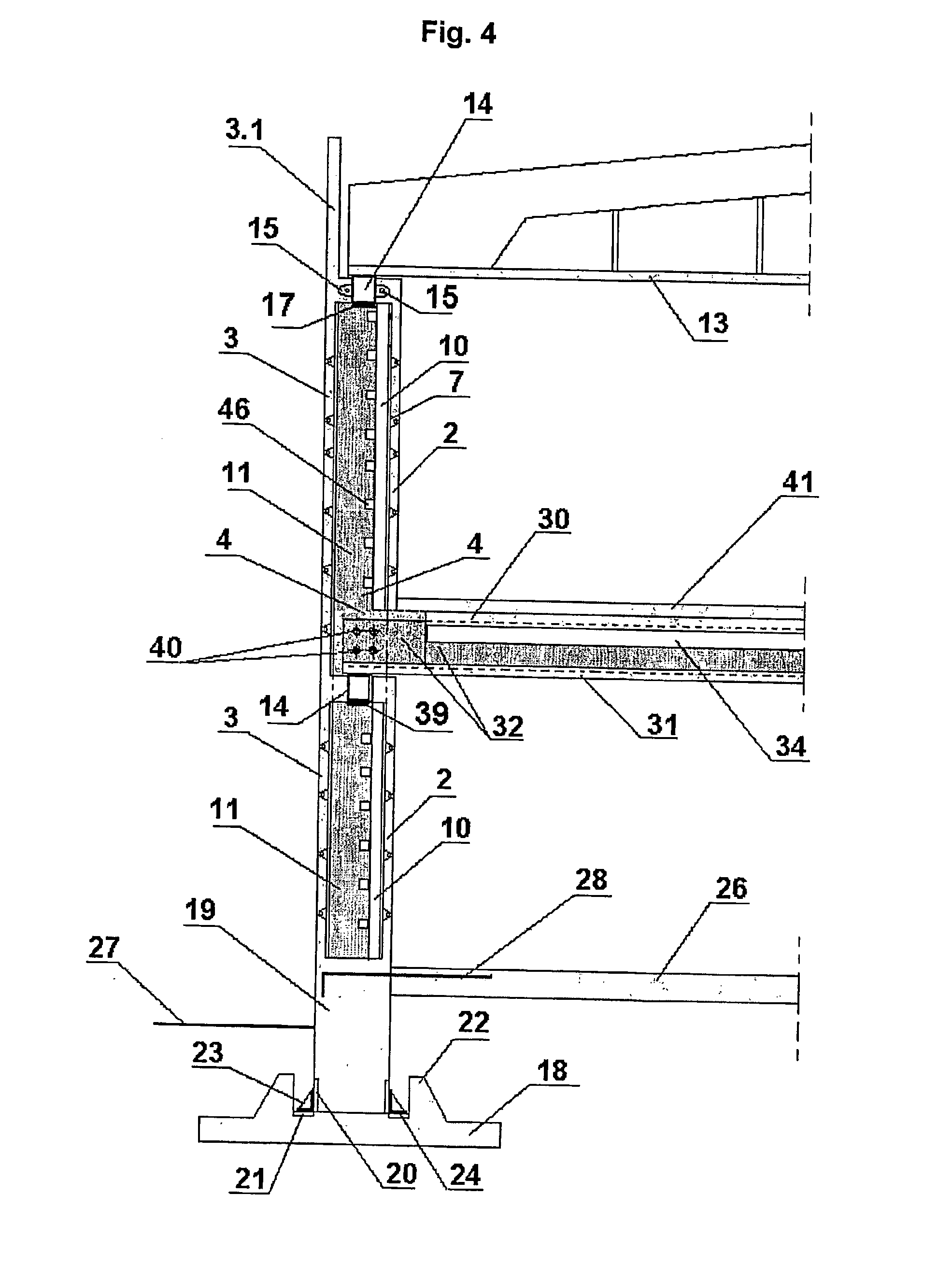
assembly) mounted as a cantilever (finally as a cantilever panel with laterally attached top), with its down-end rigidly fixed to the socket of the foundation, as shown in FIG. 11. Consequently, the lower part of the panel has a full concrete cross-section at the length which is predetermined to entry the ground and foundation, below the ground floor-plate, as shown in FIGS. 4 and 8. That is where the largest bending moments occur so the full cross section suits. One more advantage of such a solid bottom is that the wall-panel can be easily erected being rotated about its bottom whereby some chips and crushes of the bottom edges can be accepted because the bottom of the panel finally comes into a socket being poured by concrete. The creep of the capillary moisture upwards the panel can be easily prevented by a suitable external non-hygroscopic coat up to the level of the surrounding terrain. The other possible way of breaking the moisture is inbuilt moisture breaker. One more object of the invention is the method and apparatus for manufacturing such sort of panels in a rapid way making them suitable for mass production. The manufacturing method concerns with an additional device being part of the mold, providing moveable, temporary fixed bottom of the upper mold part for pouring the upper positioned concrete layer, as shown in FIGS. 9 and 10. The device comprises series of lateral sticks driven through holes in side forms of mould and through holes in steel webs of the panel. The rough-surface insulation strips are used to form the bottom of the upper mold being arranged over tops of bottom sticks, which, after concreting is done, rest one-side adhered to the concrete. After concrete of the upper concrete layer of the panel is hardened the moveable bottom is pulled aside. All the common features of the sandwich panels, that many other panels comprise, are not discussed here but only slightly mentioned because the goal of the present application was to obtain a stiff and load-bearing capable panel reliable to ensure stability of the building. Hence, until now, a reliable panel was disclosed which the real large span buildings can be constructed of.
[0011] Another building element, the composite floor unit is made in the similar way as just disclosed wall panel, shown in FIG. 5. It comprises upper and lower cast-concrete layers interconnected by two or more galvanized steel sheet strips interposed into a gap between them, anchored to the concrete in the same manner as those of wall-panel. Both concrete layers of the floor unit, s