Composite forming fabric

a technology of composite fabric and fabric, applied in the field of fabric, can solve the problems of undesired variations in sheet absorption properties, undesired wire marks, wire marks, etc., and achieve the effect of reducing the potential water carrying potential of the fabric, enhancing the binding of the paper side layer, and reducing the overall height and void volume of the fabri

Inactive Publication Date: 2006-10-19
VOITH PATENT GMBH
View PDF37 Cites 5 Cited by
  • Summary
  • Abstract
  • Description
  • Claims
  • Application Information

AI Technical Summary

Benefits of technology

[0029] In accordance with certain embodiments of the invention at least some of the binder yarns in the pairs of first and second intrinsic, interchanging yarns float under at least two adjacent wear side machine direction yarns, and if desired, under at least three adjacent wear side machine direction yarns to provide enhanced binding of the paper side layer to the machine side layer.
[0030] In addition, by floating the interchanging yarns under two or more adjacent wear side machine direction yarns, the overall height and void volume within the fabric is reduced. This reduces the potential water carrying potential of the fabric; resulting in the formation of a dryer sheet on the fabric.
[0031] In an alternative structure for providing a thin fabric with minimal delamination tendency at least some of the binder yarns of the interchanging binder yarn pairs interlace with a number of single, non-adjacent wear side MD yarn within each repeat of the weave pattern.
[0032] In all embodiments of the invention disclosed herein all or some of the wear side and/or paper side warp yarns can be of a non-circular cross section but particularly of bi-nodal (e.g., dumbbell—or “figure 8” shaped) cross-section. The bi-nodal yarn(s) is (are) extruded with the bi-nodal cross section and thus require(s) no bonding process of the type employed in the prior art, where two adjacent, but separately-formed warp yarns have been woven to an identical weave repeat. Use of bi-nodal warps, with a vertical-to-horizontal aspect ratio of at least 1:1.25, allows a thinner fabric to be provided but with the same overall cross sectional area as prior art structures. This will reduce the water

Problems solved by technology

Such localized penetration results in “wire marks” which actually is the result of fiber density variations throughout the sheet area.
Moreover, these basis weight variations can result in undesired variations in sheet absorption properties; a property very relevant to the functionality of quality graphical papers where a consistent uptake of print ink is necessary to produce a clear sharp image.
Other factors also cause the formation of undesired wire marks.
However, the use of thick yarns often causes undesirable wire marks.
The relatively high “void volume” is typically associated with sheet rewetting on the paper machine such that the sheet solids content at transfer to the press section may be undesirably low.
That is, the

Method used


Image

  • Composite forming fabric
  • Composite forming fabric
  • Composite forming fabric

Examples


Embodiment Construction

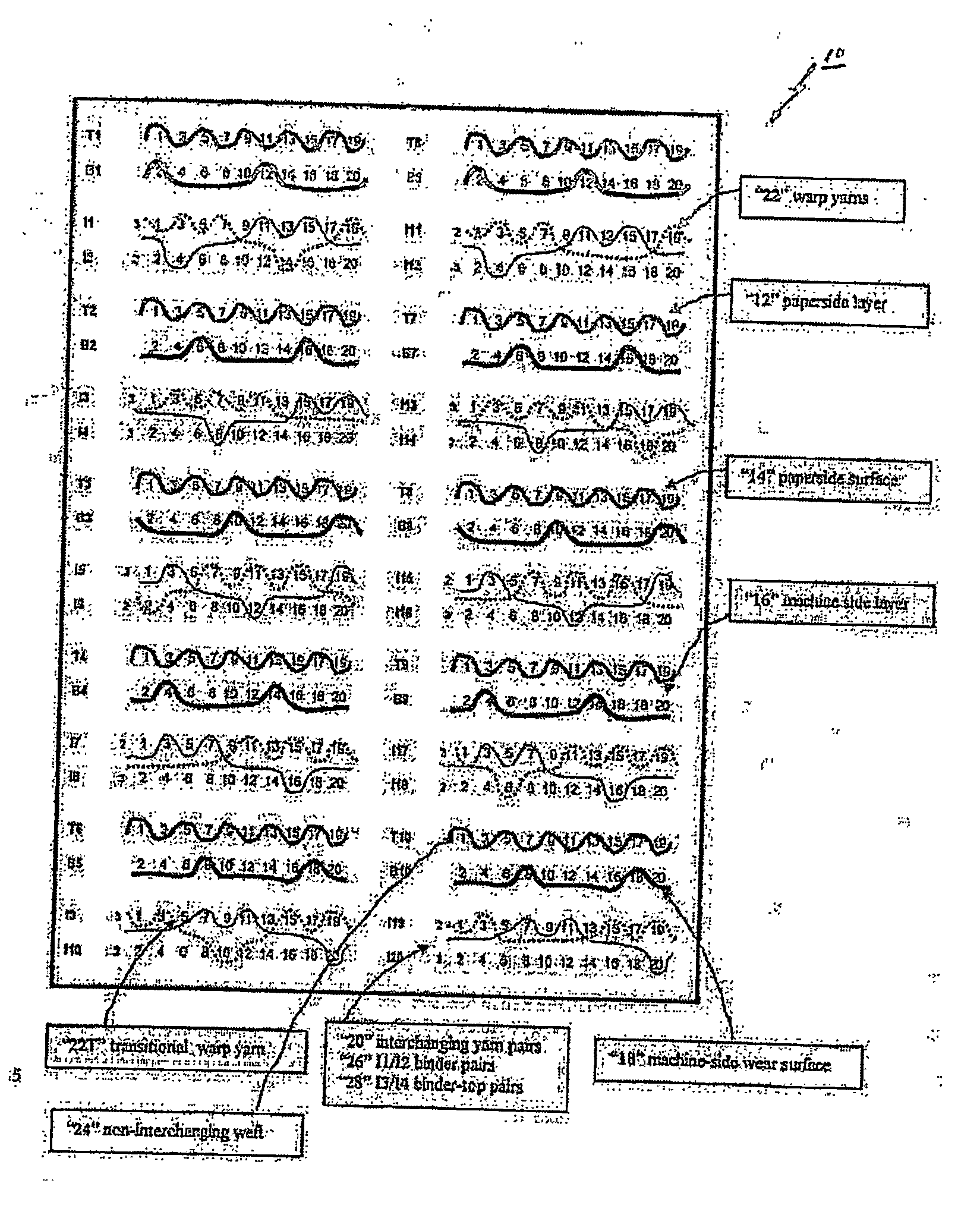
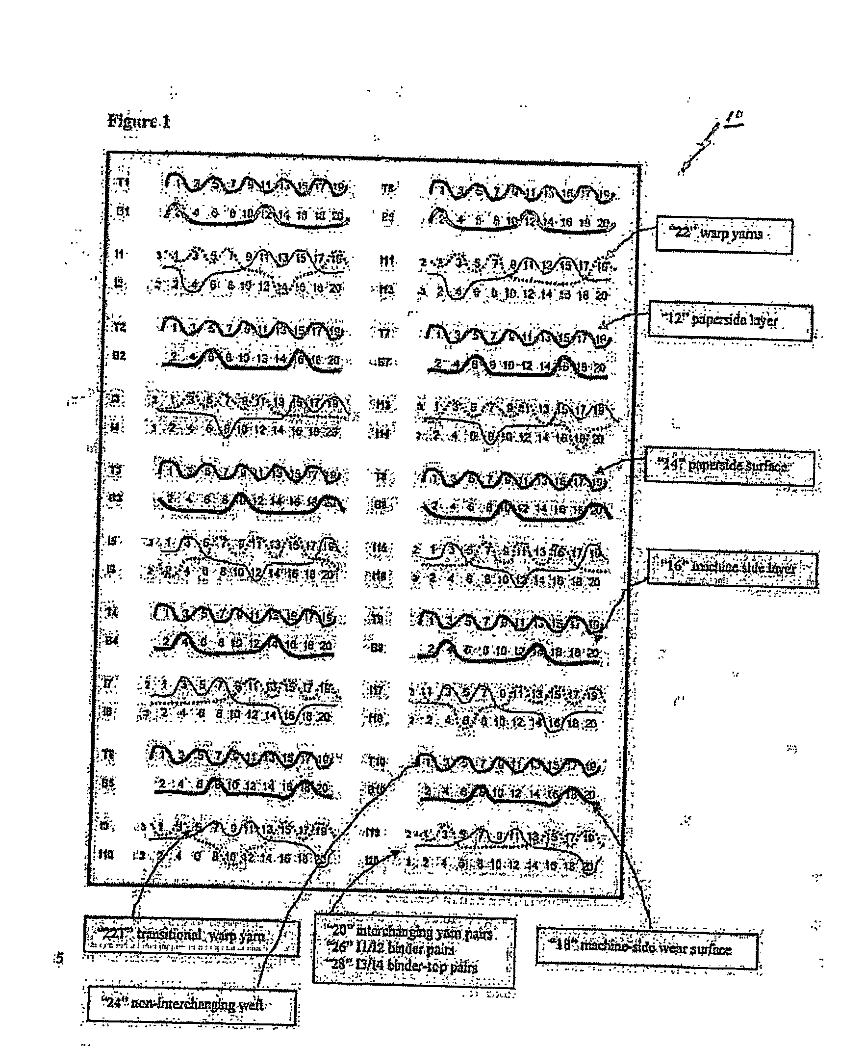
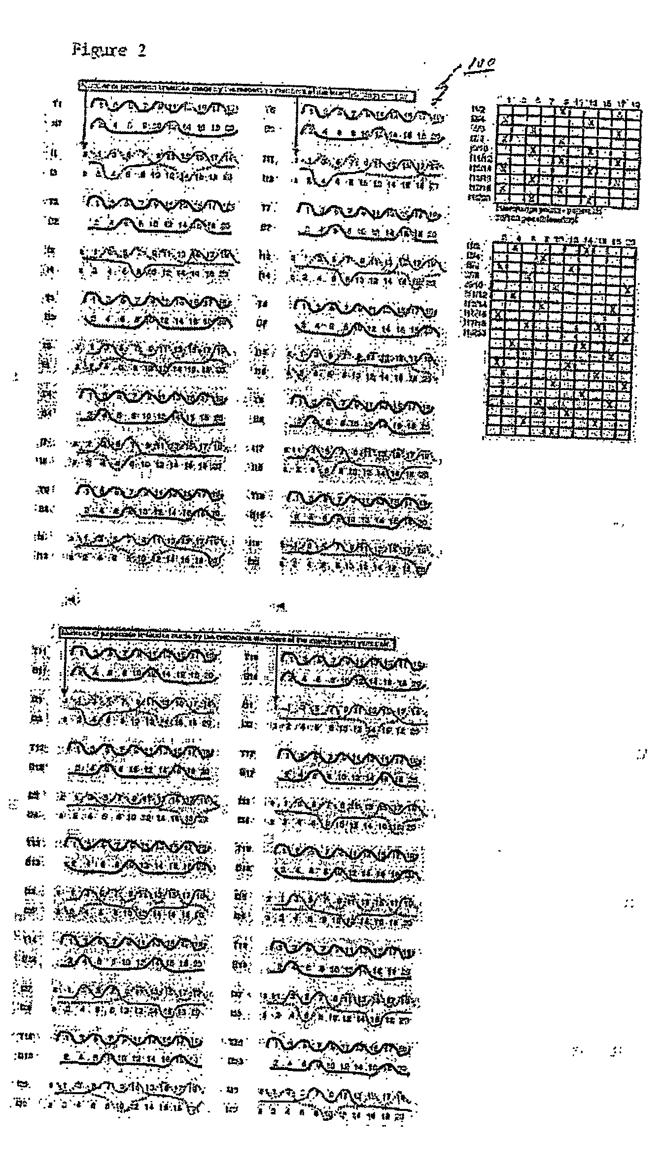
[0042] The weft paths of the paper side, wear side and interchanging yarn pairs for one preferred embodiment of a composite forming fabric 10 in accordance with this invention are shown in FIG. 1. In accordance with this embodiment, the composite forming fabric has a 20 shaft-40 pick repeat and includes a paper side layer 12 having a paper side surface 14, a machine side layer 16 having a bottom wear side surface 18 and a plurality of first and second interchanging yarns pairs, e.g., 20.

[0043] The paper side layer 12 and the machine side layer 16 each comprise a plurality of warp yarns 22 in the machine direction and plurality of non-interchanging weft yarns 24 woven together with the warp yarns. The paper side layer 12 and the machine side layer 16 each have a predetermined repeat of the weave pattern in the cross-machine direction. As illustrated, but not by a way of limitation, the illustrated composite fabric 10 is a twenty (20) shed-forty (40) pick fabric including ten (10) ma...


PUM


Abstract

A composite forming fabric comprising a paper side layer having a paper side surface, a machine side layer having a bottom wear side surface, and a plurality of pairs of first and second interchanging yarns, wherein: the paper side layer and the machine side layer each comprise warp yarns and weft yarns woven together; said paper side layer and said machine side layer each having a predetermined repeat of the weave pattern in the cross-machine-direction; each pair of first and second interchanging yarns having at least two segments in the paper side layer within each repeat of the weave pattern, said segments providing an unbroken weft path in the paper side surface, with each succeeding segment being separated in the paper side surface of the paper side layer by at least one paper side layer transitional warp yarn; at least one pair of first and second interchanging yarns within each repeat of the weave pattern being binder yarn pairs, each binder yarn in each binder yarn pair binding together the paper side layer and the machine side layer, and at least one pair of first and second interchanging within each repeat of the weave pattern being top weft/binder yarn pairs for stiffening the fabric and binding together the paper side layer and the machine side layer of the fabric.

Description

FIELD OF THE INVENTION [0001] The present invention relates to fabrics with paired, interchanging yarns, and more particularly, to fabrics employed in web forming equipment, such as papermaking and non-woven web forming equipment. More particularly, the preferred fabrics of this invention are employed as forming fabrics in web forming equipment. BACKGROUND OF THE INVENTION [0002] Papermaking involves the forming, pressing and drying of cellulosic fiber sheets. The forming process includes the step of depositing an aqueous stock solution of the fibers, and possibly other additives, onto the forming fabric upon which the initial paper web is formed. The forming fabric may run on a so-called Gap Former machine in which the aqueous stock initially is dewatered, and the initial paper sheet is formed between two forming fabrics. [0003] An effective forming process typically produces a sheet with a very regular distribution of fibers and with a relatively high solids content, i.e., a high ...

Claims


Application Information

Patent Timeline
IPC IPC(8): D03D25/00
CPCD21F1/0045
Inventor HAY, STEWART LISTER
Owner VOITH PATENT GMBH
Why Eureka
Try Eureka