Switched reluctance generator

a technology of synchronous generator and switch, which is applied in the direction of electric generator control, motor/generator/converter stopper, dynamo-electric converter control, etc., can solve the problems of complicated structure, limited limited range of wind speed at which electricity is produced, so as to reduce the number of necessary switches of sr generator and reduce production costs , the effect of simple structur

Inactive Publication Date: 2006-10-19
LG ELECTRONICS INC
View PDF39 Cites 31 Cited by
  • Summary
  • Abstract
  • Description
  • Claims
  • Application Information

AI Technical Summary

Benefits of technology

[0020] Therefore, the number of necessary switches of the SR generator is r

Problems solved by technology

Although conventional wind power stations have widely used an induction generator or a synchronous generator, the induction generator must maintain a predetermined speed when generating electricity whereas it has a simple structure and a low production cost, such that it requires an additional gearbox and has a limited range of wind velocity at which electricity is generated.
The synchronous generator

Method used


Image

  • Switched reluctance generator
  • Switched reluctance generator
  • Switched reluctance generator

Examples


Embodiment Construction

[0032] Now, preferred embodiments of the present invention will be described in detail with reference to the annexed drawings. In the drawings, the same or similar elements are denoted by the same reference numerals even though they are depicted in different drawings. In the following description, a detailed description of known functions and configurations incorporated herein will be omitted when it may make the subject matter of the present invention rather unclear.

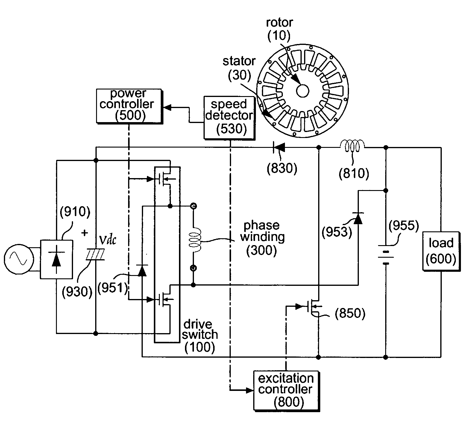
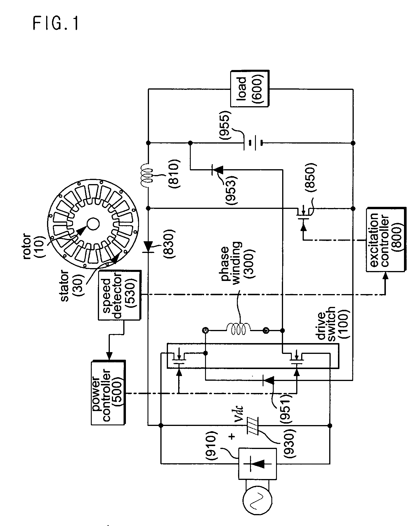
[0033]FIG. 1 is a circuit diagram illustrating an SR generator in accordance with a preferred embodiment of the present invention. Referring to FIG. 1, the SR generator includes a rotor 10, a stator 30 on which a phase winding 300 is wound, a drive switch 100 for controlling a current signal flowing in the phase winding 300, and a power controller 500 for controlling a switching operation of the drive switch 100.

[0034] The SR generator must initially receive an excitation current. For this purpose, an independent gene...


PUM


Abstract

A Switched Reluctance (SR) generator having improved efficiency at low and high speed is disclosed. The SR generator includes a step-up converter for controlling an excitation voltage of an excitation capacitor capable of providing a phase winding with an excitation current. Therefore, the SR generator can control the excitation current, and can provide a phase winding with a sufficient excitation current, thereby improving efficiency. The step-up converter is arranged between a battery capable of storing generated power and the excitation capacitor, boosts a voltage of the battery, and provides the excitation capacitor with the boosted voltage. Therefore, the SR generator does not include an additional power-supply unit for a boosting function, resulting in simplification of an overall structure and reduction of a production cost.

Description

BACKGROUND OF THE INVENTION [0001] 1. Field of the Invention [0002] The present invention relates to a Switched Reluctance (SR) generator, and a more particularly to an SR generator for improving generation performance at low and high speed. [0003] 2. Description of the Related Art [0004] Generally, an SR generator has been widely used as an energy conversion device, such that it transmits electric energy from a voltage source to a winding having one or more phases via an electric switching operation during a predetermined rotor angle period, and takes more electric energy than that received in the winding from the winding during the remaining rotor angle periods. The above-mentioned additional energy is indicative of mechanical energy applied to a generator rotor when torque is rotationally applied to the SR generator. The SR generator has an output signal configured in the form of a current source, so that it can generate electricity. [0005] Although conventional wind power statio...

Claims


Application Information

Patent Timeline
IPC IPC(8): H02K7/18H02K19/24H02K19/36H02P9/30
CPCH02P9/00H02P25/18H02P25/085H02P25/092E06B3/6604E06B3/5454E06B3/64E06B7/02E06B7/12
Inventor LIM, JUN-YOUNGCHOI, YONG-WON
Owner LG ELECTRONICS INC
Why Eureka
Try Eureka