Solution method and apparatus for large-scale simulation of layered formations

a technology of layered formations and solutions, applied in the field of computerized simulation of hydrocarbon reservoirs, can solve the problems of large and complex simulation models of reservoirs and oil/gas fields, limited time step size, and high recursive nature of procedures, and is not conducive to parallel implementation

Active Publication Date: 2006-10-19
SAUDI ARABIAN OIL CO
View PDF14 Cites 127 Cited by
  • Summary
  • Abstract
  • Description
  • Claims
  • Application Information

AI Technical Summary

Benefits of technology

[0019] Briefly, the present invention provides a new and improved method of computerized simulation of state changes of fluids in underground layered formations in the earth. A formation layer of the underground formations is partitioned into a grid formed of a number of laterally contiguous grid cells. Representations of state changes for the grid cells with adjacent grid cells are established for the laterally contiguous grid cells.

Problems solved by technology

Simulation models of reservoirs and oil / gas fields have become increasingly large and complex.
IMPES solved one equation (the pressure equation) per grid block per time step implicitly and was far cheaper computationally than FI, but had stability limitations which constrained the time step size.
The procedure was highly recursive in nature and was not conducive to parallel implementation.
In reality, many reasons can cause the solution time on a real system to be far from this ideal.
This posed limits on the scalability inherent to this type of extension.
This could lead to interpretation problems, verification problems, and added uncertainty in the results.
In general, the existing methods had significant dependency on the number of processors used in parallel to solve a problem.
For the same problem, a parallel simulation had an added level of global iterations in parallel processing which increased the processing complexity of the work.
This lead to a loss of efficiency as processor count increased.
This could lead to interpretation problems, verification problems, and added uncertainty in the results.

Method used


Image

  • Solution method and apparatus for large-scale simulation of layered formations
  • Solution method and apparatus for large-scale simulation of layered formations
  • Solution method and apparatus for large-scale simulation of layered formations

Examples


Embodiment Construction

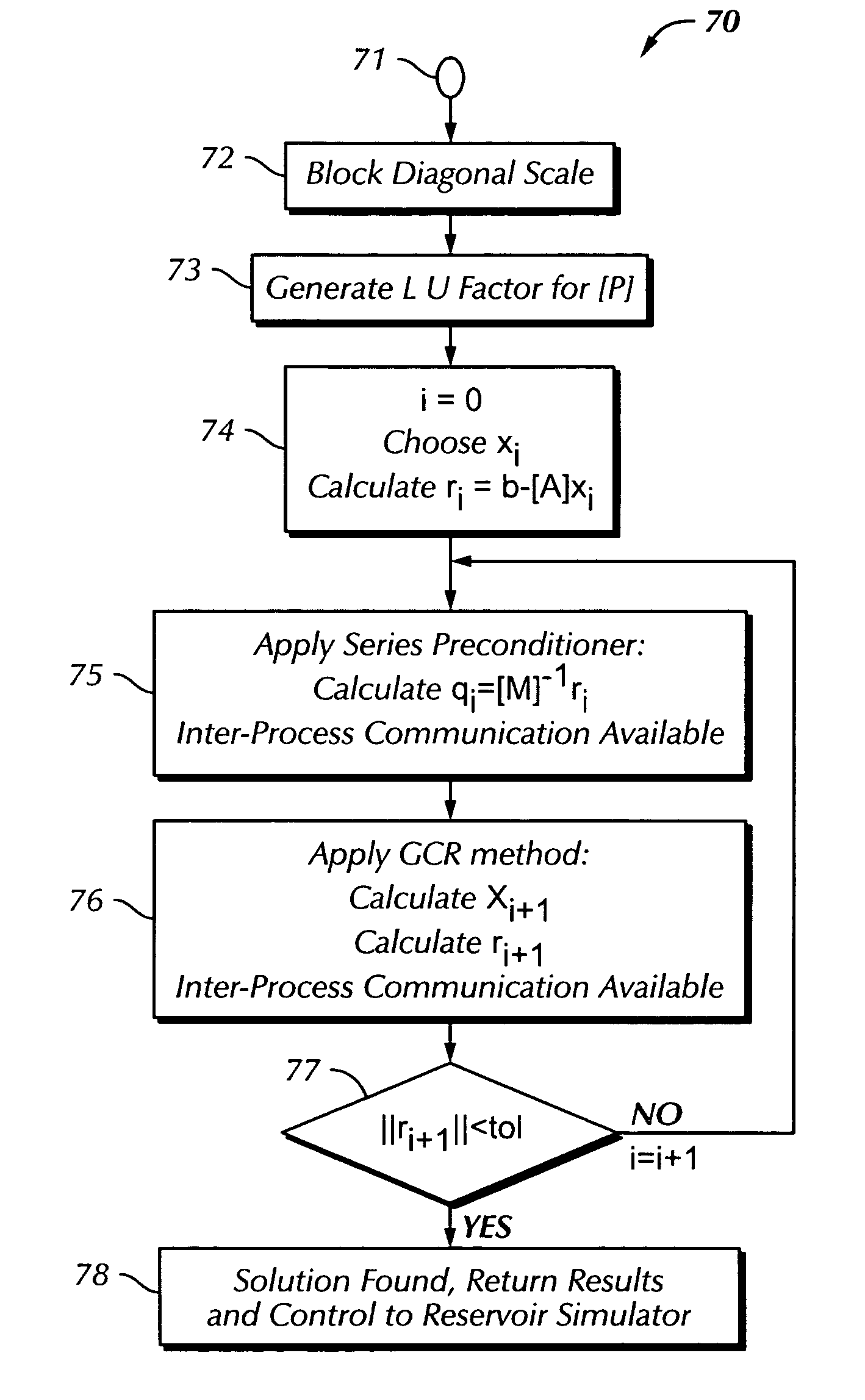
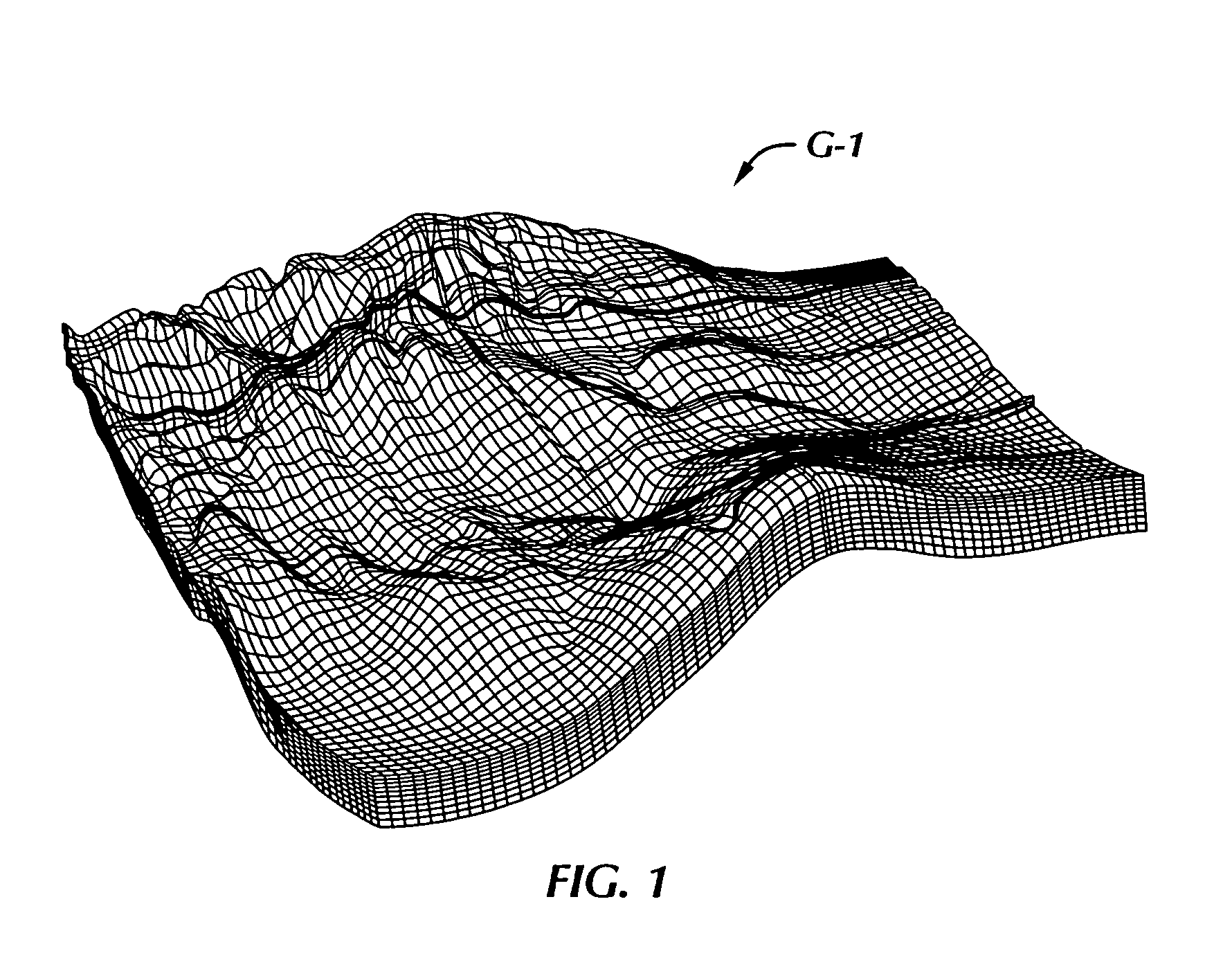
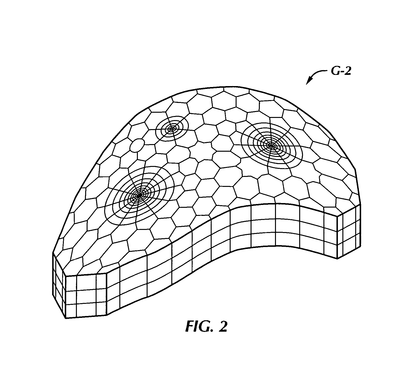
[0036] The method in the present invention solves a linear system of equations arising from a typical structured or semi-unstructured discretization of a fluid flow model in a layered heterogeneous porous geological formation in the underground. A particular application is in a reservoir simulator which models the changes over time (transient) of material balance and fluid flow behaviors of a multiple component, multiple phase system involving hydrocarbon fluids plus groundwater. The formation is typically a very large one, which ha been partitioned into a grid formed of a number of laterally contiguous grid cells. The number of grid cells normally is in the hundreds of thousands to several millions in a typical field-scale simulation. For each grid cell, a multi-equation system for tracking the material balance of each fluid component and fluid phase pressure is used.

[0037] Typically, the formation geometry is such that the lateral extent (typically in kilometers) is orders of mag...


PUM


Abstract

A targeted heterogeneous medium in the form of an underground layered formation is gridded into a layered structured grid or a layered semi-unstructured grid. The structured grid can be of the irregular corner-point-geometry grid type or the simple Cartesian grid type. The semi-unstructured grid is areally unstructured, formed by arbitrarily connected control-volumes derived from the dual grid of a suitable triangulation; but the connectivity pattern does not change from layer to layer. Problems with determining fluid movement and other state changes in the formation are solved by exploiting the layered structure of the medium. The techniques are particularly suited for large-scale simulation by parallel processing on a supercomputer with multiple central processing units (CPU's).

Description

BACKGROUND OF THE INVENTION [0001] 1. Field of Invention [0002] The present invention relates to computerized simulation of hydrocarbon reservoirs in the earth, and in particular to simulation of fluid movement and other state changes in hydrocarbon reservoirs formed of layered formations. [0003] 2. Description of the Prior Art [0004] In the oil and gas industries, the development of underground hydrocarbon reservoirs often requires the building of computer simulation models. These underground hydrocarbon reservoirs are often complex rock formations which contain both a petroleum fluid mixture and water, with the reservoir fluid content, often existing in two or more fluid phases. The petroleum mixture is produced by wells drilled into and completed in these rock formations. [0005] Reservoir simulation belongs to the general domain of simulation of flow in porous media. However, reservoir simulation normally involves multiple hydrocarbon components and multiple fluid phases in an un...

Claims


Application Information

Patent Timeline
Patent Type & Authority Applications(United States)
IPC IPC(8): G06G7/48G06F30/00
CPCE21B49/00G06F2217/16G06F17/5018G06F2111/10G06F30/23
Inventor FUNG, LARRY S.AL-SHAALAN, TAREQ M.
Owner SAUDI ARABIAN OIL CO
Why Eureka
Try Eureka