Supercharge Your Innovation With Domain-Expert AI Agents!

Scan-based self-test structure and method using weighted scan-enable signals

a self-testing and scan-enabled technology, applied in the direction of electronic circuit testing, measurement devices, instruments, etc., can solve the problems of high hardware overhead and relatively short test time required by such self-testing structures, and achieve the effect of convenient implementation

Inactive Publication Date: 2006-10-19
TSINGHUA UNIV
View PDF5 Cites 10 Cited by
  • Summary
  • Abstract
  • Description
  • Claims
  • Application Information

AI Technical Summary

Benefits of technology

[0055] The present invention combines the scan-based self-test technique and the weighted random test technique, and achieves the objective of the generation of weighted random test vectors by using weighted enable signals. This strategy has the advantage that test responses at any clock can be collected, and easily implemented, where any four extra gates are sufficient to implement the weighted scan enable signal based scan-based BIST scheme. Further, the implementation of this technique does not need to modify the hardware of the existing self-test architectures, general purpose pseudo-random test pattern generators and test response compactor are suitable for the present invention.

Problems solved by technology

In the test-per-clock mode, application of a test vector and test response compression are completed in one clock, and testing time required by such self-test structure is relatively short, but hardware overhead required to implement it is very high; as for the test-per-scan BIST, a test vector under is applied into the scan chains through the phase shifter (all scan flip-flops in a scan chain is controlled by the same scan enable signals, wherein it is 1 during the scan shift mode, and 0 for the capture cycle for all scan flip-flops to receive test responses).

Method used


Image

  • Scan-based self-test structure and method using weighted scan-enable signals
  • Scan-based self-test structure and method using weighted scan-enable signals
  • Scan-based self-test structure and method using weighted scan-enable signals

Examples


Embodiment Construction

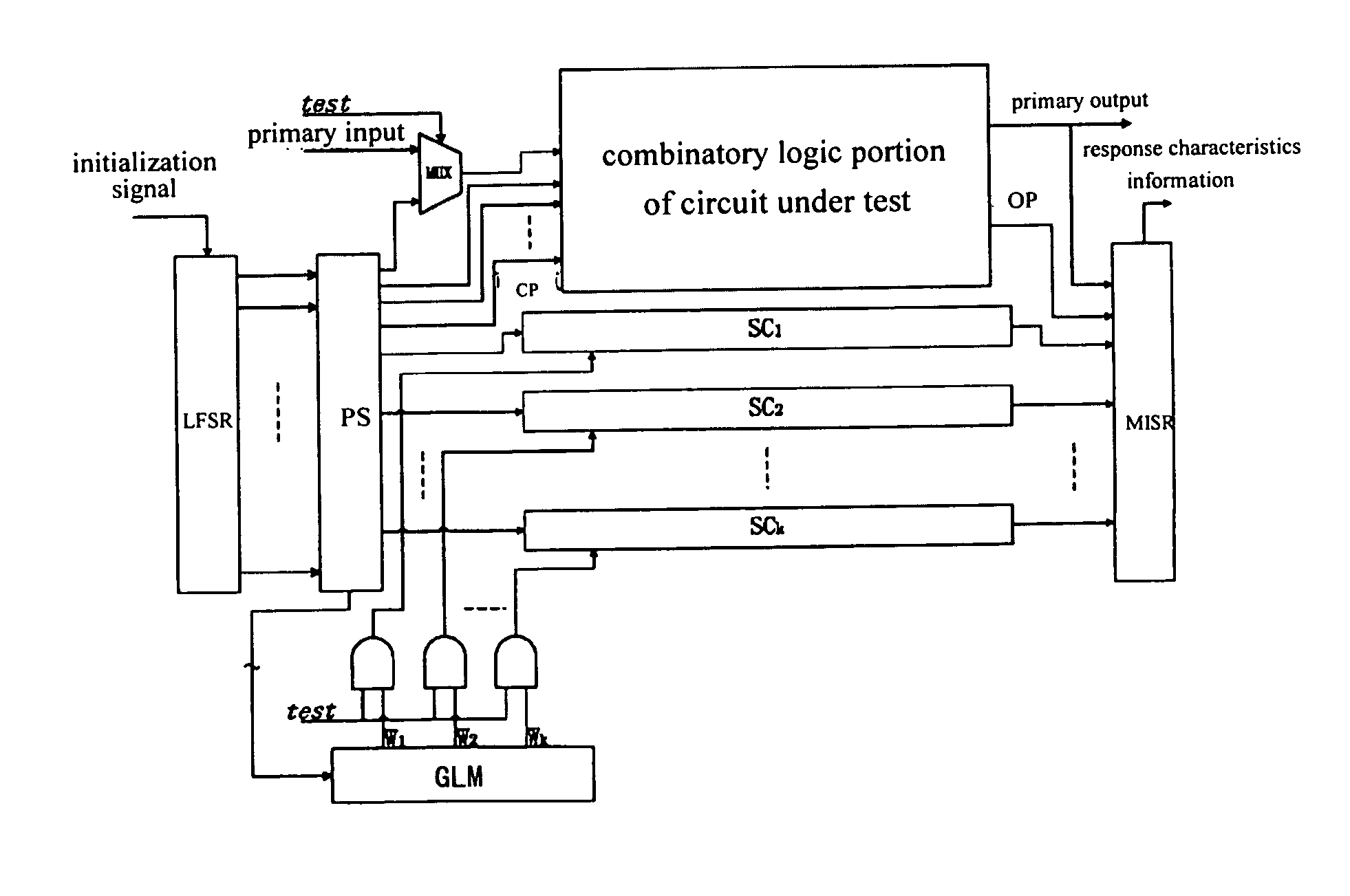
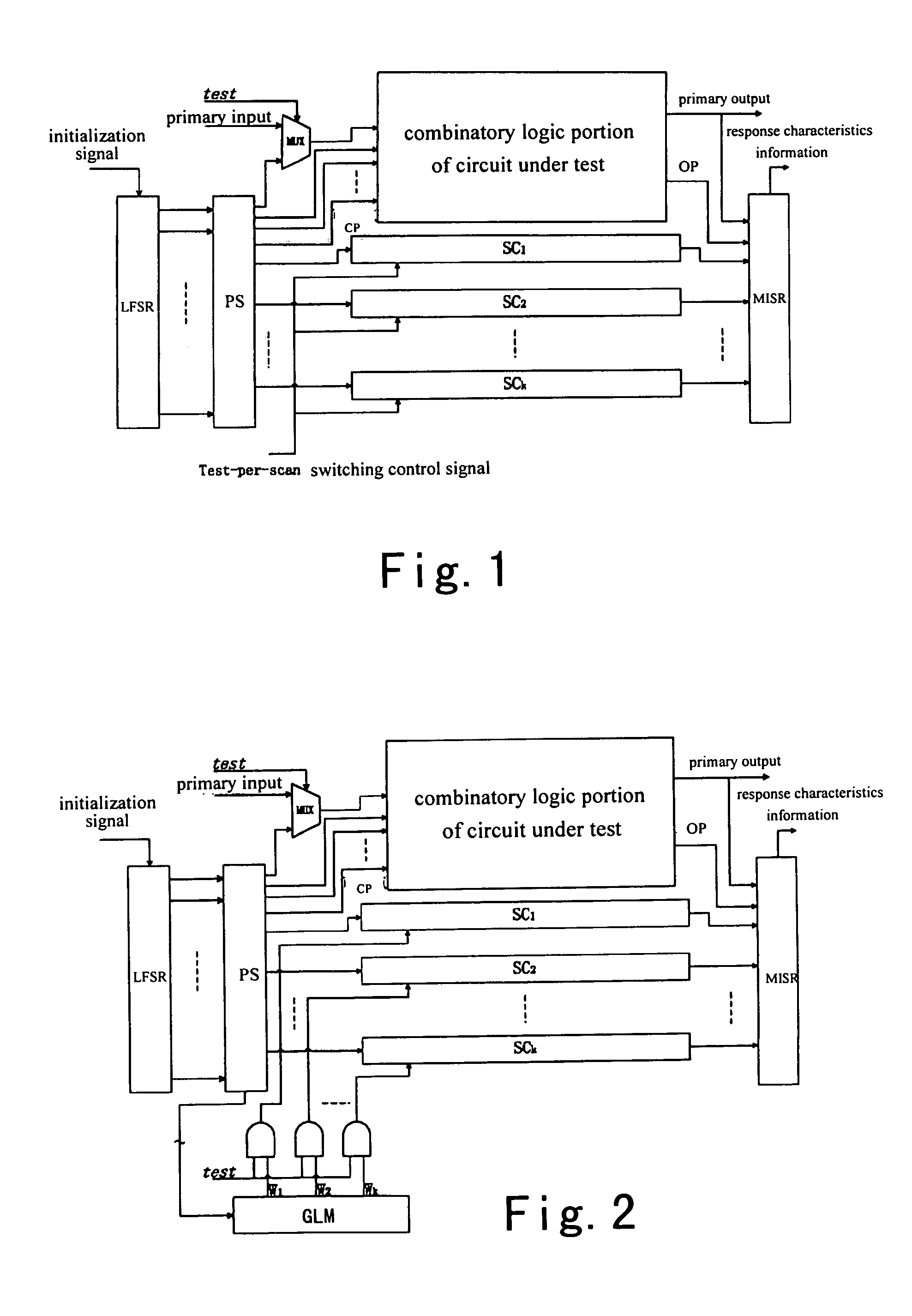
[0063]FIG. 2 shows a basic block diagram of the circuit structure according to an embodiment of the present invention. Weights W1, W2, . . . , Wk ∈ {0.5, 0.625, 0.75, 0.85} are assigned to scan enable signals of scan chains SC1, SC2, . . . , SCk respectively. MUX represents a multiplexer. The selected weights are connected to the scan enable signals of the scan chains through k AND gate. One input of each AND gate is a switch signal for switching between a test mode and a normal operation mode, which is marked as test. When test=1, the system is in the test mode, and weighted scan enable signals are applied to the scan chains to generate weighted test pattern; when test=0, the system turns to the normal operation mode.

[0064] It is essential to select appropriate weights for the scan chains as shown in FIG. 2. This may affect final test results of the circuit. The present embodiment provides an algorithm and a circuit testability gain function. Selection of weights assigned to the s...


PUM


Abstract

A scan-based self-test architecture and method using weighted scan enable signals is disclosed. The self-test architecture comprises: a linear feedback shift register; a phase shifter connected to outputs of the linear feedback shift register, and scan chains and the combinational part of the circuit under test; an AND gate; scan chains, each being formed by serially connecting multiple scan flip-flops having the same architecture; a multiplexer; and a logic unit for generating weighted random signal, whose inputs are connected with the phase shifter; the logic unit randomly selects the input pseudo random signals, weights the selected pseudo random signals, and assigns the weighted pseudo random signals assigned to the scan enable signals of the scan chains, to control the switching of the scan chains between the scan shift mode and the functional mode. The test effectiveness of scan-based BIST can be improved greatly using the test scheme with weighted scan enable signals.

Description

FIELD OF THE INVENTION [0001] The present invention relates to test technique of integrated circuit and, more particularly to scan-based self-test structure and scheme using weighted scan-enable signals. BACKGROUND OF THE INVENTION [0002] The scan-based self-test technique (scan-based BIST) is a design technique for enhanced testability of synchronous circuits, which combines the traditional built-in self-test technique with the scan design technique to enhance the test effectiveness of digital systems. In the built-in self-test technique, a pseudo-random test pattern generator and a test response compressing logic are embedded into the circuit, where a phase shifter (PS) is also added to reduce the interdependence test signals generated by separate stages of the pseudo-random test pattern generator. The new invention is an effective means to reduce testing time and testing cost of the chips. The scan design makes flip-flops in the circuit controllable and observable and connects th...

Claims


Application Information

Patent Timeline
IPC IPC(8): G01R31/28G01R31/317G01R31/3185
CPCG01R31/318544G01R31/31701
Inventor XIANG, DONGSUN, JIAGUANGCHEN, MINGJING
Owner TSINGHUA UNIV
Features
  • R&D
  • Intellectual Property
  • Life Sciences
  • Materials
  • Tech Scout
  • Unparalleled Data Quality
  • Higher Quality Content
  • 60% Fewer Hallucinations
Learn More