Spacing-saving superconducting device

Inactive Publication Date: 2006-10-26
SIEMENS AG
View PDF18 Cites 56 Cited by
  • Summary
  • Abstract
  • Description
  • Claims
  • Application Information

AI Technical Summary

Benefits of technology

[0015] This object is achieved by a superconducting device having a magnet with at least one superconducting winding, a cryogenic unit with at least one cryogenic head and a conduction system with at least one conduit for a cryogenic agent (circulating therein according to a thermo-siphon effect) for indirectly thermally coupling the at least one winding to the cryogenic head, with the cryogenic head being located below a highest point of the at least one winding. This prevents the aforementioned disadvantage of known thermo-siphon cooling systems, wherein the cryogenic unit is arranged above the windings. The magnet thus can be fashioned larger in comparison with such known solutions. Given room heights in the range of 2.5 to 3 m in which magnetic resonance apparatuses are typically to be installed, the laterally-arranged cryogenic unit allows approximately 40 to 50 cm more space to be available for the diameter of the magnet than in known solutions with thermo-siphon cooling. The entire room height is available for accommodation of the magnet or an insulation reservoir in which the magnet is located (as the largest unit of the magnetic resonance apparatus).

Problems solved by technology

Upon an operating interruption of the magnets, an unintended transition of initially superconducting parts of the magnets into the normal conductive state can occur, causing the magnet-heat in an avalanche effect.
This results in high production costs and, in the case of magnetic resonance apparatuses, has the additional disadvantage that the distance between the magnet and a patient is increased.
Bath cooling, moreover, has the disadvantage that multiple hundreds of liters of fluid helium are required to cool the magnet, that are lost in the event of a quench.
This leads to increased costs for the operator of the magnetic resonance apparatus.
This is particularly disadvantageous in the case of magnets for magnetic resonance apparatuses, since these are generally to be installed in rooms with established headroom (2.5 to 3 meters).
This in turn has a disadvantageous effect on the flux density of the magnet and therewith on the imaging properties of the magnetic resonance apparatus.
In principle, this could be compensated by an increase of the number of windings or of the ratio of the superconducting material to a corresponding wire, but neither approach is practical due to cost reasons.
Depending on the distance between the cryogenic head and the object to be cooled, the large cross-sections required for a sufficiently good thermal coupling then lead to a considerable increase of the cryogenic mass.
This is particularly disadvantageous in the spatially extensive magnet systems that are typical in magnetic resonance apparatuses due to the extended cooling times.
Since the cryogenic head is arranged next to the winding, it is not possible to fill the conduit completely with liquid helium.

Method used


Image

  • Spacing-saving superconducting device
  • Spacing-saving superconducting device
  • Spacing-saving superconducting device

Examples


Embodiment Construction

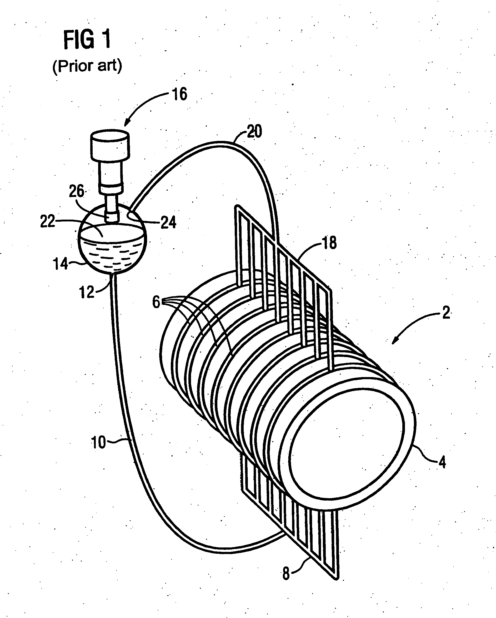
[0029]FIG. 1 shows a superconducting magnet 2 with a cooling system in a schematic perspective representation. An arrangement of the shown type is, for example, known from DE 33 44 046 C2. The magnet 2 is cylindrical and has a number of superconducting windings that are not shown here. The windings are wound around a coil body 4 in a known manner, for example within recesses. Conduits 6 for accommodation of a cryogenic agent (for example liquid helium) are embedded in a number of cross-section planes of the coil body 4. The conduits 6 are copper tubes. For embedding they can alternatively run in further recesses around the coil body 4 and exhibit a good thermal contact with the coil body 4. The thermal contact can be achieved by known techniques such as welding, force fitting, casting or bonding. Stainless steel or aluminum can also be used as alternative materials for the conduits 6. Cooling of the coil body 4 and the superconducting windings is achieved with liquid helium located ...


PUM


Abstract

A superconducting device has a magnet with at least one superconducting winding and a cryogenic unit that has at least one cryogenic head. The device further has a conductor system with at least one conduit for a cryogenic agent (circulating therein according to a thermo-siphon effect) for indirect thermal coupling of the at least one winding to the at least one cryogenic head. The cryogenic head is below a highest-situated point of the at least one winding.

Description

BACKGROUND OF THE INVENTION [0001] 1. Field of the Invention [0002] The present invention concerns a superconducting device of the type having a magnet with at least one superconducting winding cryogenic unit having at least one cryogenic head, and a conductor system with at least one conduit for a cryogenic agent (circulating therein according to a thermo-siphon effect) for indirectly thermally coupling the at least one winding to the at least one cryogenic head. [0003] 2. Description of the Prior Art. [0004] In general, liquid helium is used for cooling superconducting magnets, in particular in magnetic resonance apparatuses. The superconducting magnet is located in a bath composed of liquid helium (see U.S. Patent No. 6,246,308). Magnets with cryogenic units are available in which vaporized helium is condensed so that losses of helium are precluded as much as possible. The magnets are surrounded by pressure reservoirs that also contain the liquid helium. Upon an operating interru...

Claims


Application Information

Patent Timeline
IPC IPC(8): F25D23/12F17C9/02F28D15/00
CPCF25B23/006H01F27/2876H01F6/04G01R33/3815F25B31/00F25D3/10
Inventor STEINMEYER, FLORIAN
Owner SIEMENS AG
Why Eureka
Try Eureka