Ridigly mounted underwater acoustic inertial vector sensor

a technology inertial vector sensors, which is applied in the field of underwater acoustic sensors, can solve the problems of inaccurate measurement of acoustic fields which depart from perfect plane wave behavior, decrease the dynamic range of the probe, and increase so as to reduce the scattering effect of the body and the effect of greater accuracy

Inactive Publication Date: 2006-10-26
PENN STATE RES FOUND
View PDF14 Cites 14 Cited by
  • Summary
  • Abstract
  • Description
  • Claims
  • Application Information

AI Technical Summary

Benefits of technology

[0013] In contrast with the probes of the prior art, a neutrally buoyant probe according to preferred embodiments of the present invention directly measure both acoustic velocity and pressure. More importantly, the some embodiments of the invention provide a probe whose dynamics are such that motion of a central support rod is essentially zero in the frequency band of interest. Consequently, the rod can be rigidly mounted to an existing support structure with no effect on the probe's response to acoustic excitation. The probe provides for a true

Problems solved by technology

The distance the hydrophones are set apart can cause inaccurate measurements.
Setting the hydrophones too closely together greatly decreases the dynamic range of the probe.
Setting the hydrophones too far apart can result in the inaccurate measurement of acoustic fields which depart from perfect plane wave behavior.
While both of these probes may potentially measure acoustic intensity, the probe of U.S. Pat. No. 3,311,873 disregards the inertial e

Method used


Image

  • Ridigly mounted underwater acoustic inertial vector sensor
  • Ridigly mounted underwater acoustic inertial vector sensor
  • Ridigly mounted underwater acoustic inertial vector sensor

Examples


Embodiment Construction

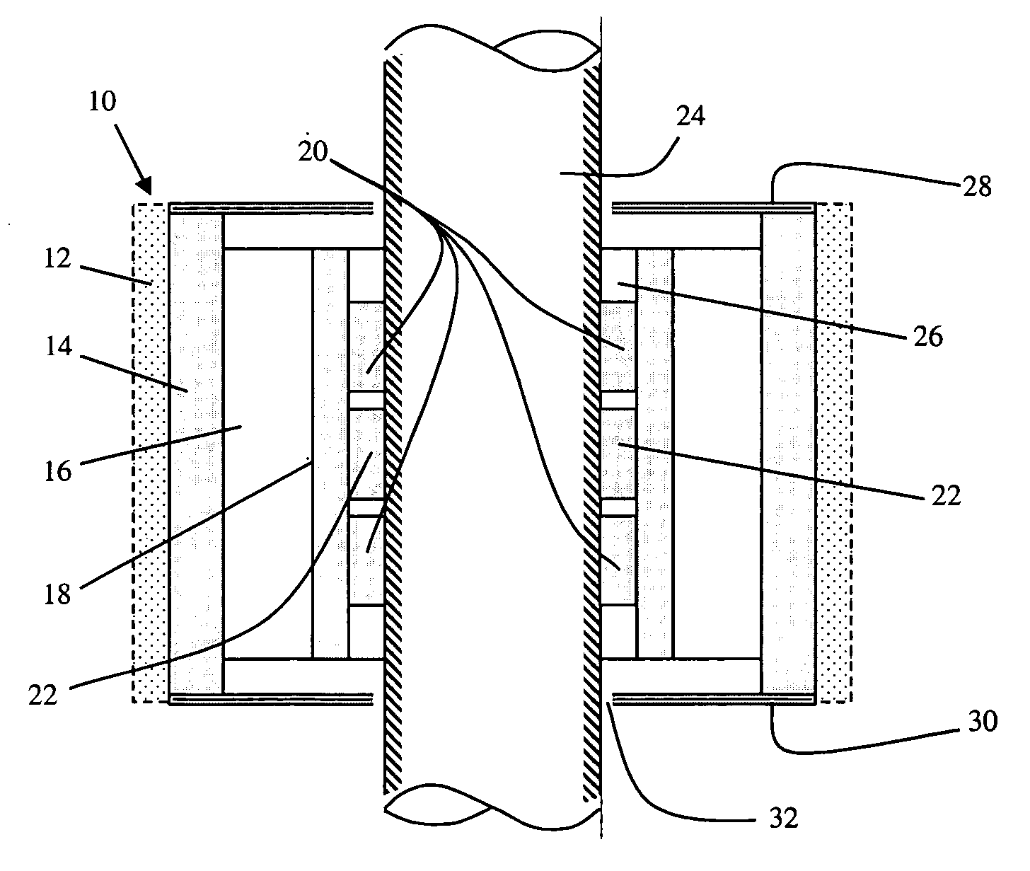
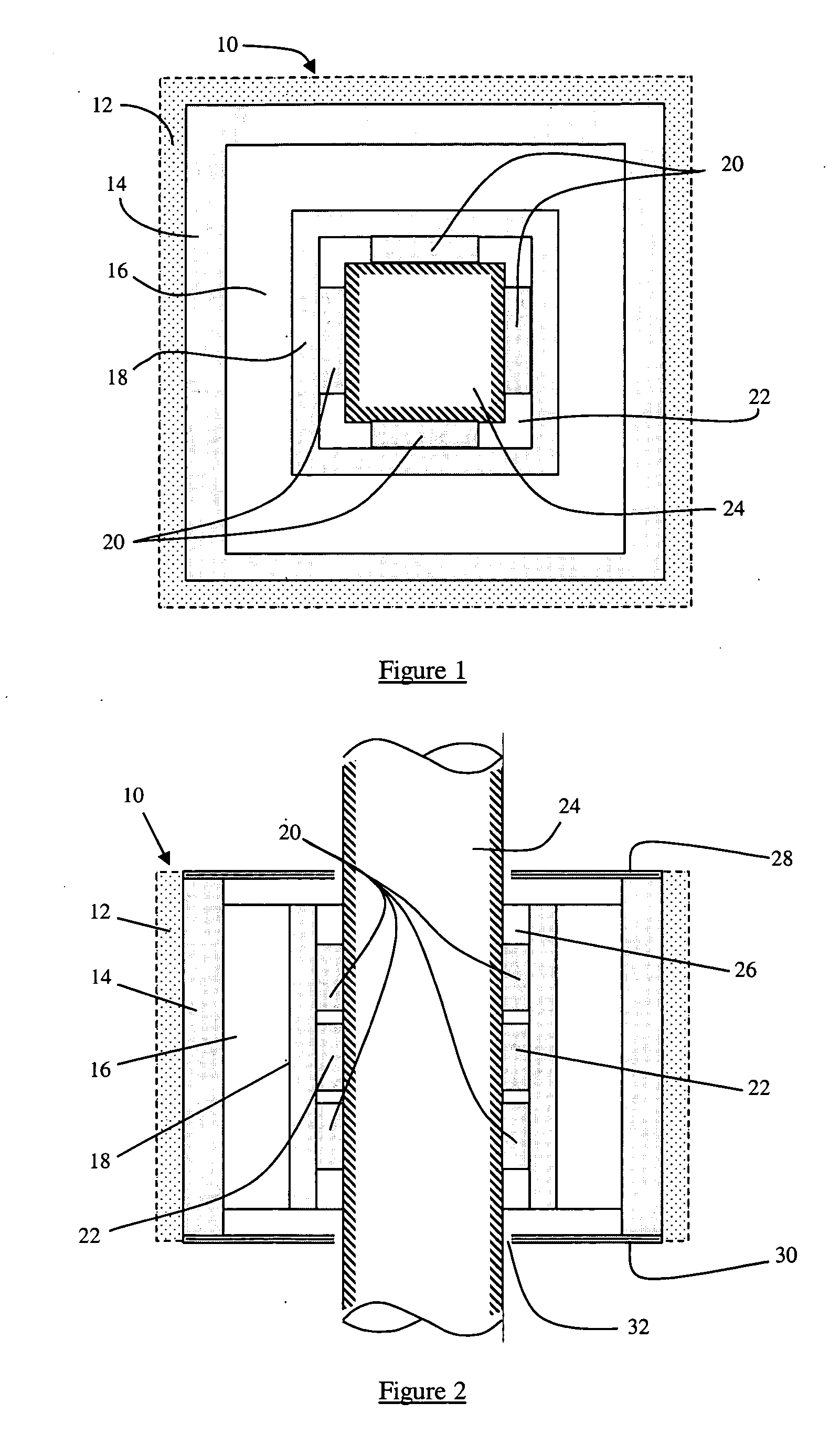
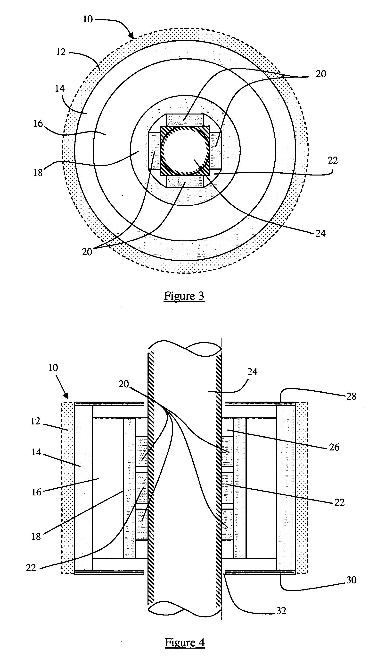
[0028] A probe 10 for use underwater to measure true acoustic intensity is shown generally in FIGS. 1 and 2. The outer casing of probe 10 is preferably made neutrally buoyant, such that wave vibrations affect the probe casing 14 just as they would affect the water which probe 10 displaces. Probe casing 14 may include a syntactic foam casting 12. The cured foam can be used, trimmed or weighted to achieve neutral buoyancy, as needed. While it is preferred that the outer casing be made neutrally buoyant, embodiments of the present invention may be made without a neutrally buoyant outer casing. A compliance layer 16 separates the probe outer casing 14 from a “coupling-mass” or secondary casing 18. The compliance layer may take a variety of forms, and in this embodiment is a thin layer of compliant rubber, such as a silicon rubber. A plurality of sensor elements 20 and 22 are disposed between the inner surface of the “coupling-mass” or secondary casing 18 and a central mounting structure...


PUM


Abstract

An underwater acoustic sensor is designed for attachment to a rigid or semi-rigid mounting structure. The sensor includes an outer casing and a secondary casing spaced therefrom. A compliance layer is disposed between the inner surface of the outer casing and the outer surface of the secondary casing. An inner sensor support is designed to attach to the mounting structure and is spaced from the inner surface of the secondary casing. A plurality of sensor elements are disposed between and interconnect the inner surface of the secondary casing and the sensor support.

Description

REFERENCE TO RELATED APPLICATION [0001] This application claims priority from U.S. Provisional Patent Application Ser. No. 60 / 630,676, filed Nov. 23, 2004, the entire content of which is incorporated herein by reference.STATEMENT OF GOVERNMENT INTEREST [0002] The invention described herein was made with Government support under Contract No. N00014-03-1-0863 awarded by the Office of Naval Research. The United States Governmental has certain rights in this invention.FIELD OF THE INVENTION [0003] The present invention relates generally to underwater acoustic sensors. BACKGROUND OF THE INVENTION [0004] Conventional underwater probes are suspended in a body of water, carried onboard a vessel, or are allowed to rest upon the floor of a body of water. The measurements that these probes provide can be used to determine the nature of noise emission from underwater sources such as those generated from natural (weather, geological, or biologically-related) or man-made processes. For instance, ...

Claims


Application Information

Patent Timeline
IPC IPC(8): G01H11/00G01N29/00
CPCG01N2291/02827G01H11/00
Inventor NALUAI, NATHAN K.LAUCHLE, GERALD C.
Owner PENN STATE RES FOUND
Why Eureka
Try Eureka