Timing control circuit for an optical recording apparatus

a timing control circuit and optical recording technology, applied in the direction of recording signal processing, generating/distributing signals, instruments, etc., can solve the problems of increasing writing speed, data errors may occur, and the severity of the above-mentioned problems, so as to reduce phase variations, reduce time differences, and eliminate or eliminate the effect of data

Inactive Publication Date: 2006-10-26
KONINKLIJKE PHILIPS ELECTRONICS NV
View PDF13 Cites 2 Cited by
  • Summary
  • Abstract
  • Description
  • Claims
  • Application Information

AI Technical Summary

Benefits of technology

[0008] According to an important aspect of the present invention, this objective is attained by providing an automatic alignment between edges of the clock signal and edges of the data signal. This will eliminate or at least reduce phase variations such as for instance caused by process spread, temperature variations, and power supply variations.

Problems solved by technology

If these requirements are not met, data errors may occur.
The problems mentioned above have increasing severity with increasing writing speed (data rate).

Method used


Image

  • Timing control circuit for an optical recording apparatus
  • Timing control circuit for an optical recording apparatus
  • Timing control circuit for an optical recording apparatus

Examples


Embodiment Construction

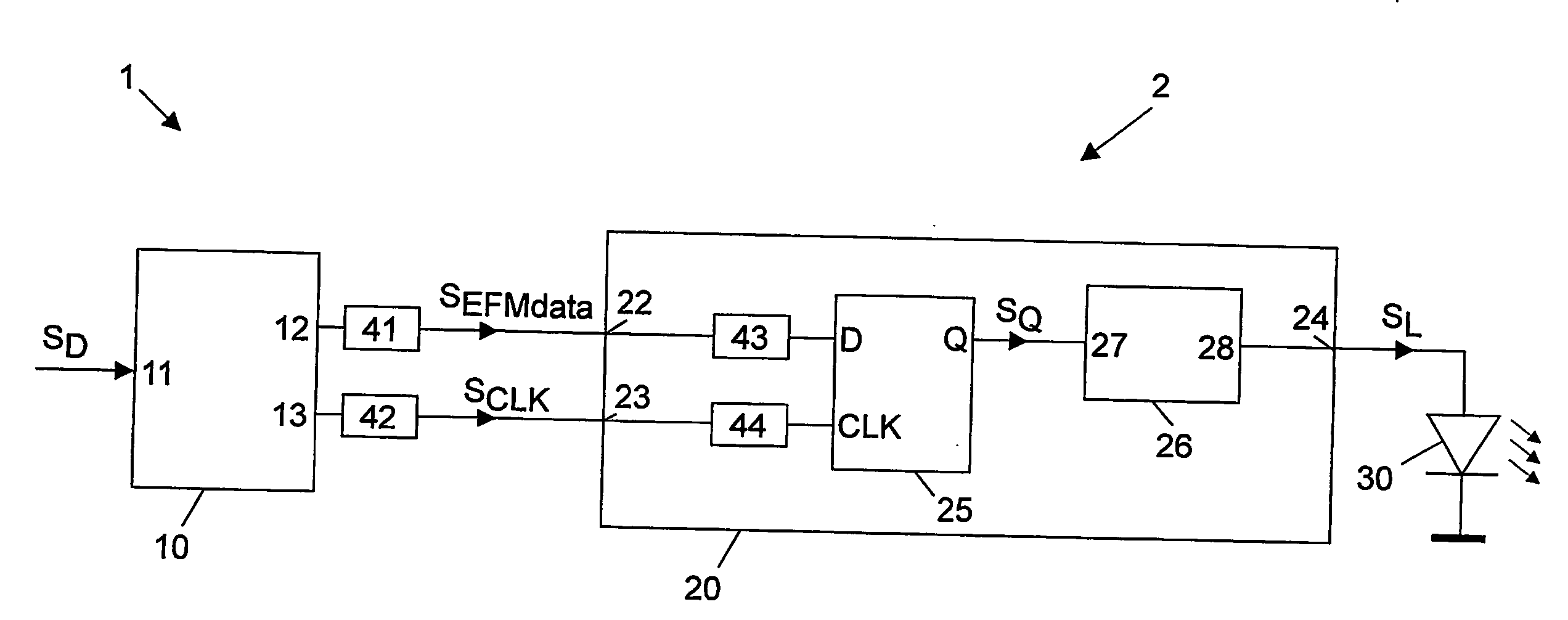
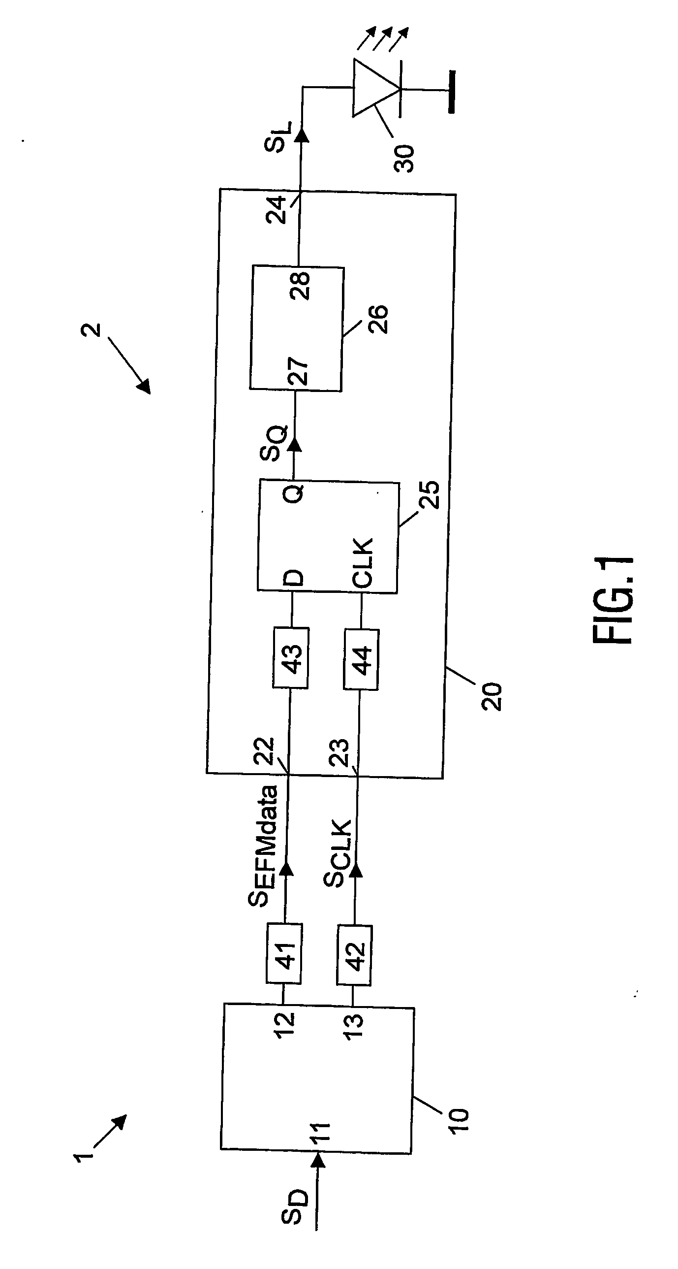
[0015]FIG. 1 schematically shows an optical writing system 2 of an optical disc writing apparatus 1. The optical writing system 2 comprises an encoder device 10 having an input 11 for receiving a data signal SD from a data source not shown for sake of simplicity. The encoder 10 performs a coding operation, typically the well-known eight-to-fourteen modulation coding (EFM), and provides an EFM data signal SEFMdata at a data output 12 and an EFM clock signal SCLK at a clock output 13. Since eight-to-fourteen modulation coding is known per se, it is not necessary here to explain this coding scheme in detail.

[0016] The optical writing system 2 further comprises a laser diode 30 and a driver circuit 20 for driving the laser diode 30. The driver circuit 20 has a data input 22 coupled to the data output 12 of the encoder 10 for receiving the data signal SEFMdata, and has a clock input 23 coupled to the clock output 13 of the encoder 10 for receiving the clock signal SCLK. The driver circu...


PUM

PropertyMeasurementUnit
delay timeaaaaaaaaaa
fixed delay timeaaaaaaaaaa
timeaaaaaaaaaa

Abstract

An optical recording apparatus (1) is described, for writing information into an optical storage medium such as for instance an optical storage disc, the apparatus comprising a laser diode (30) and a laser diode driver circuit (20), which laser diode driver circuit (20) comprises a flipflop device (25), a write strategy generator and a laser current driver (26), and a timing control circuit (50). The flipflop receives a digital data signal and a digital clock signal. The timing control circuit (50) either delays the digital data signal or the digital clock signal, such as to substantially align data signal edges with passive clock signal edges.

Description

FIELD OF THE INVENTION [0001] The present invention relates in general to an optical recording apparatus for writing information into an optical storage medium, more particularly but not necessarily exclusively an optical storage disc. Specifically, the present invention relates to a timing control circuit for an optical recording apparatus. Hereinafter, the present invention will be explained for the case of an optical storage disc, and the apparatus will also be indicated as “optical disc drive”. BACKGROUND OF THE INVENTION [0002] As is commonly known, an optical storage disc comprises at least one track, either in the form of a continuous spiral or in the form of multiple concentric circles, of storage space where information may be stored in the form of a data pattern. Optical discs may be read-only type, where information is recorded during manufacturing, which information can only be read by a user. The optical storage disc may also be a writable type, where information may be...

Claims


Application Information

Patent Timeline
Patent Type & Authority Applications(United States)
IPC IPC(8): G02B5/22G06F1/10G11B7/0045G11B7/09G11B20/10G11C7/22H03L7/06H03L7/081
CPCG11B7/0045H03L7/0812G11B20/10194G11B7/09G11C7/22G06F1/10H03L7/06
Inventor LOOIJKENS, MARINUS ADRIANUS HENRICUSMCCORMACK, JAMES JOSEPH ANTHONY
Owner KONINKLIJKE PHILIPS ELECTRONICS NV
Why Eureka
Try Eureka