Laser apparatus and method for assembling the same

Inactive Publication Date: 2006-10-26
ADTEC ENG +1
View PDF2 Cites 31 Cited by
  • Summary
  • Abstract
  • Description
  • Claims
  • Application Information

AI Technical Summary

Benefits of technology

[0033] (2) In particular, in the case where one or more fixing members to which the one or more semiconductor lasers are fixed are also fixed to the package with solder, heat can be satisfactorily dissipated from the one or more fixing members to the package, and therefore the effect of preventing the deterioration of the output levels and the lifetimes is further enhanced.
[0034] On the other hand, in the case where one or more fixing members to which optical components constituting an optical condensing system are fixed are fixed to the package with solder, the precision of the positions of the one or more fixing members with respect to the package is likely to be lower than the precision of the positions of one or more fixing members fixed to the package with an adhesive. However, when the optical components constituting the optical condensing system are fixed to the one or more fixing members with an adhesive in such a manner that the optical components are precisely aligned with the optical fiber, the low precision of the positions of the one or more fixing members to which the optical components are fixed causes no problem.
[0035] (3) In the case where one or more holders are fixed to one or more fixing members which are fixed to the package, and one or more optical components constituting the optical condensing system are fixed to the one or more holders in the laser apparatus according to the first aspect of the present invention, it is possible to adjust the positions of the one or more holders by moving the one or more holders along the one or more fixing members, and adjust the positions of the one or more optical components by moving the one or more optical components al

Problems solved by technology

However, in the case where semiconductor lasers and optical components are fixed to a package or fixing members fixed to the package as mentioned above, with an adhesive or solder, the output levels or the lifetimes of the semiconductor lasers deteriorate, and the error of the position of the condensing

Method used


Image

  • Laser apparatus and method for assembling the same
  • Laser apparatus and method for assembling the same
  • Laser apparatus and method for assembling the same

Examples


embodiment

Advantages of Embodiment

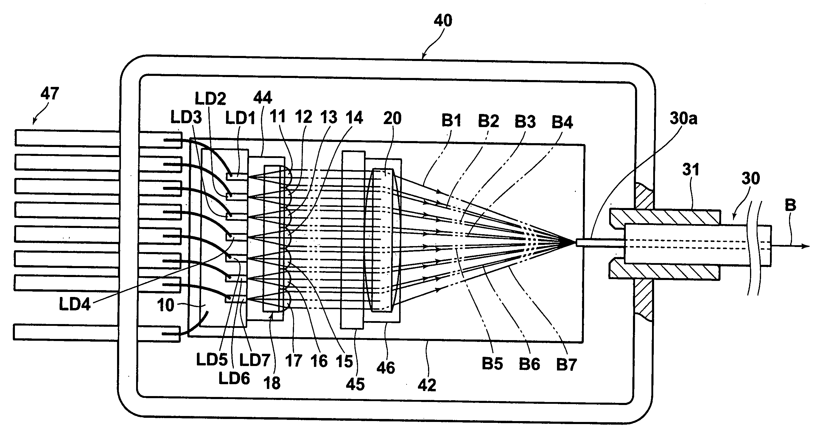
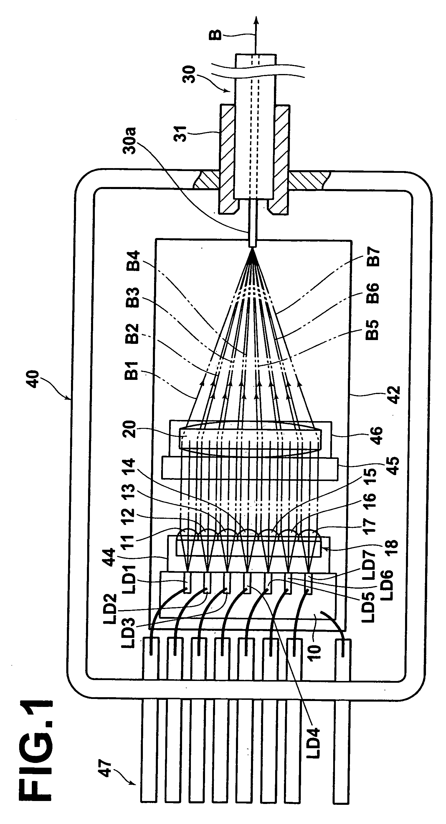
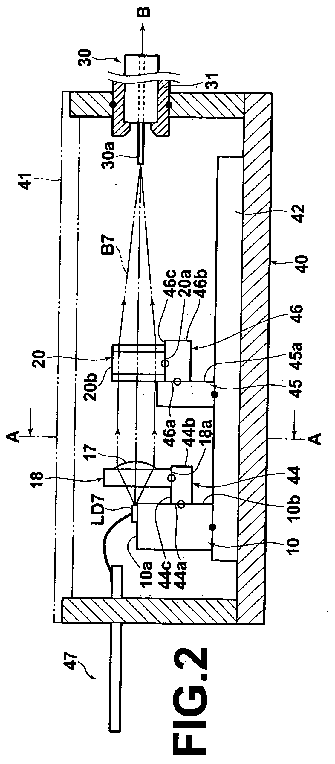
[0103] (1) As explained above, the condensing lens 20 is fixed to the condensing-lens holder 46 so that the optical axis of the condensing lens 20 precisely coincides with the optical axis of the near-end portion of the multimode optical fiber 30. In addition, the collimator-lens array 18 is fixed so that the optical axes of the collimator lenses 11 through 17 are precisely parallel to the optical axis of the near-end portion of the multimode optical fiber 30. Therefore, it is possible to ensure high coupling efficiency of the laser beams B1 through B7 to the multimode optical fiber 30.

[0104] (2) In the combined laser apparatus according to the present embodiment, the GaN-based semiconductor lasers LD1 through LD7 are fixed to the heat block 10 with Sn—Au solder. Since the Sn—Au solder exhibits high thermal conductivity, the heat generated by the GaN-based semiconductor lasers LD1 through LD7 can be satisfactorily dissipated through the Sn—Au solder to the h...


PUM


Abstract

A laser apparatus includes: one or more semiconductor lasers emitting one or more laser beams; an optical fiber; an optical condensing system which makes the one or more laser beams enter the optical fiber from a light-entrance end of the optical fiber; and a package which fixedly contains the optical condensing system and the one or more semiconductor lasers, and fixedly holds the optical fiber in such a manner that the light-entrance end faces the optical condensing system. The one or more semiconductor lasers are directly or indirectly fixed to the package with solder, and the one or more optical components are directly or indirectly fixed to the package with a thin layer of adhesive having a thickness of less than or equal to 1 micrometer, and preferably a thickness within a range of 0.2 micrometers to 1 micrometer after being dried.

Description

BACKGROUND OF THE INVENTION [0001] 1. Field of the Invention [0002] The present invention relates to a laser apparatus in which one or more laser beams emitted from one or more semiconductor lasers contained in a package are optically combined in an optical fiber. The present invention also relates to a method for assembling the above laser apparatus. [0003] 2. Description of the Related Art [0004] Some known types of laser apparatuses optically combine a plurality of laser beams in a single optical fiber, and output a high-power laser beam by inputting the plurality of laser beams into the single optical fiber. For example, such laser apparatuses are disclosed in Japanese Unexamined Patent Publication Nos. 2003-347647 and 2004-045667. The disclosed laser apparatuses are basically constituted by one or more semiconductor lasers which emit a plurality of laser beams, a single optical fiber, and an optical condensing system which condenses the plurality of laser beams and makes the co...

Claims


Application Information

Patent Timeline
IPC IPC(8): H01S3/04G02B6/32
CPCG02B6/4204G02B6/4238G02B6/4249H01S5/005H01S5/4031H01S5/02272H01S5/02284H01S5/4012H01S5/02208H01L2224/48091H01L2224/48247H01S5/02251H01S5/0237H01L2924/00014
Inventor YOSHIDA, TAKASHINAGANO, KAZUHIKOOKAZAKI, YOJI
Owner ADTEC ENG
Why Eureka
Try Eureka