Pneumatically static balancer for machine tool
- Summary
- Abstract
- Description
- Claims
- Application Information
AI Technical Summary
Benefits of technology
Problems solved by technology
Method used
Image
Examples
first embodiment
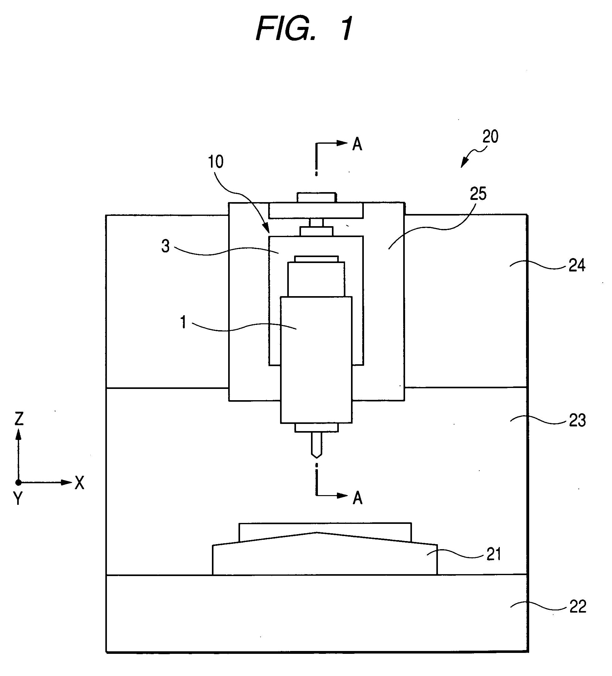
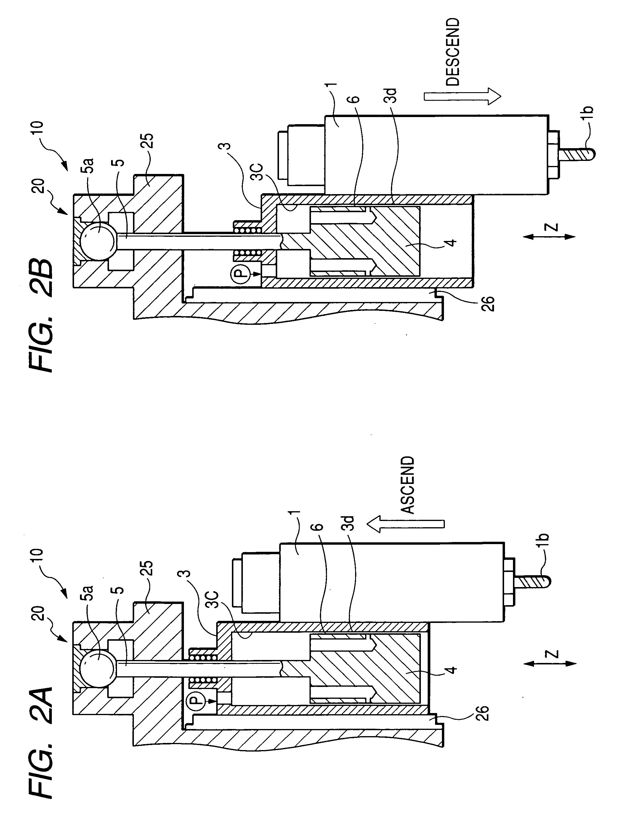
[0052]FIG. 3 is a sectional view showing a first embodiment and is taken along line A-A of FIG. 1. As shown in FIG. 3, the sliding portion of the pneumatic cylinder 3 for passing the cylinder rod 5 therethrough is provided with a ball guide bushing 8.
[0053] Once the compressed air flows from an air pressure source P such as a compression pump into the interior 3c of the pneumatic cylinder 3, the pneumatic cylinder 3 is ascended by a pressure P1 to counterbalance or lightening the gravitational load which is generated by the weight of the main spindle head 1 or the pneumatic cylinder 3.
[0054] The piston 4 is provided with a plurality of air communication holes 4a, each of which has its one end opened to communicate with the cylinder interior 3c of the pneumatic cylinder 3. In the piston 4, there is formed static pressure nozzles 4b, which communicate with the air communication holes 4a from the outer peripheral portion of the piston 4. Via the static pressure nozzles 4b, the compre...
second embodiment
[0060]FIG. 4 is a sectional view showing a second embodiment and is taken along line A-A of FIG. 1. As shown in FIG. 4, this second embodiment is characterized in that the piston 4 shown in FIG. 3 further includes a ring groove 4d, which is positioned on the upper side of vicinity of the central portion thereof. This ring groove 4d is provided with such an air exhaust 4e for the pneumatically static bearing 6 as extends radially inward. In the piston 4, on the other hand, an air exhaust 4f to communicate with the air exhaust 4e is formed to extend axially upward from the lower end face of the piston 4. The air exhaust 4f is connected to a valve 9g (as located on the right side of the drawing). In other words, the air exhausts 4e and 4f constitute a air exhaust passage having a first hole on the ring groove and a second hole on a lower face of the piston. The second hole connects the air exhaust passage with the valve 9g. The ring groove 4d is formed at a substantially intermediate p...
third embodiment
[0062]FIGS. 5A and 5B show a third embodiment, FIG. 5A is a sectional view taken along line A-A of FIG. 1, and FIG. 5B is a sectional view taken along line B-B of FIG. 5A. As shown in FIG. 5B, vertically extending vertical grooves 4g are formed in the outer circumference of the piston 4. These vertical grooves 4g are formed in plurality (e.g., twelve) and arranged equidistantly in the circumferential direction of the piston 4. As shown in FIG. 5A, the vertical grooves 4g have their lower end portions formed into a not-go shape. Specifically, the vertical grooves 4g are not provided entirely of the axial direction of the piston 4 but are formed to extend from the upper end of the piston 4 but to stop short of the lower end. At the lower end portion of the piston 4, moreover, there is formed a cylindrical face 4h which does not have the vertical grooves 4g. In short, the lower ends of the vertical grooves 4g do not reach to the lower end of the piston 4. According to this constitution...
PUM
| Property | Measurement | Unit |
|---|---|---|
| Weight | aaaaa | aaaaa |
Abstract
Description
Claims
Application Information
 - R&D
- Intellectual Property
- Life Sciences
- Materials
- Tech Scout
- Unparalleled Data Quality
- Higher Quality Content
- 60% Fewer Hallucinations
Browse by: Latest US Patents, China's latest patents, Technical Efficacy Thesaurus, Application Domain, Technology Topic, Popular Technical Reports.
© 2025 PatSnap. All rights reserved.Legal|Privacy policy|Modern Slavery Act Transparency Statement|Sitemap|About US| Contact US: help@patsnap.com


