Stabilizer bar

a stabilizer bar and tube technology, applied in the field of tube stabilizer bars, can solve the problems of reducing the fatigue life of components, overall hardness, ultimate tensile strength, and brittleness, and achieve the effects of reducing manufacturing costs, increasing hardness, and improving fatigue li

Inactive Publication Date: 2006-11-02
MERITOR SUSPENSION SYST U S
View PDF1 Cites 44 Cited by
  • Summary
  • Abstract
  • Description
  • Claims
  • Application Information

AI Technical Summary

Benefits of technology

[0008] By eliminating tempering from a stabilizer bar manufacturing process, manufacturing costs are reduced. Further, the as-quenched stabilizer bar provides increased hardness and significantly improved fatigue life, without compromising ductility, when compared to prior designs.

Problems solved by technology

Quenching produces martensite, which is very hard but brittle.
Brittle material has a tendency to crack, which can result in an overall reduction in fatigue life of a component.
One disadvantage with this tempering process is that while brittleness is reduced, the overall hardness, ultimate tensile strength, and yield strength are also reduced.
Further, the stabilizer bar made according to this process has a hardness value that is typically around 37 Rockwell C. This combination of properties provides a less than desired fatigue life for a stabilizer bar.

Method used


Image

  • Stabilizer bar
  • Stabilizer bar

Examples


Embodiment Construction

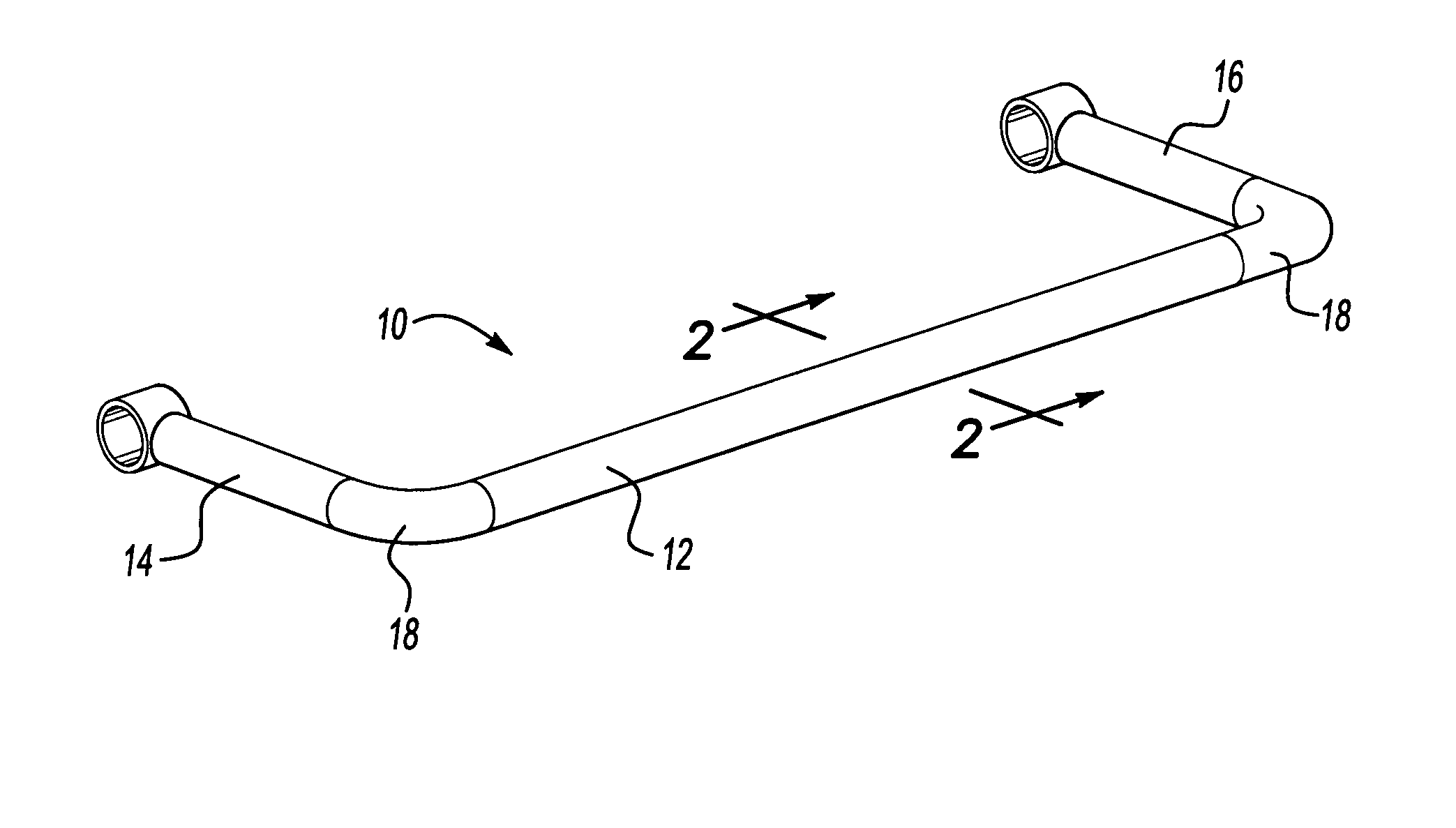
[0012] A stabilizer bar is shown generally at 10 in FIG. 1. The stabilizer bar 10 is formed to have a U-shape with a center portion 12 and first and second transversely extending legs 14, 16. Radiused bends 18 transition from the center portion 12 to the first and second transversely extending legs 14, 16. The first and second transversely extending legs 14, 16 are each attached to a suspension trailing arm or lower control arm (not shown) as known.

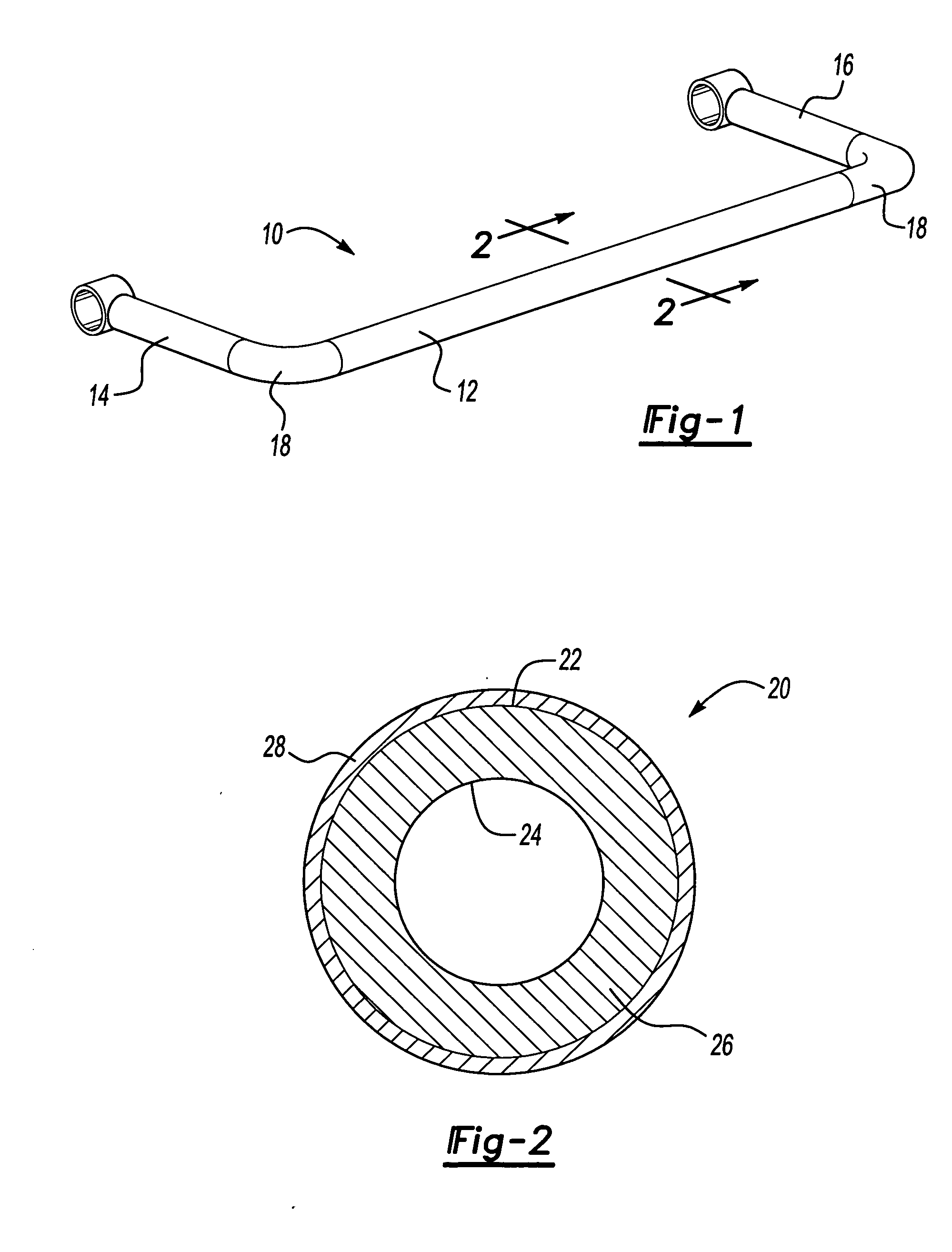
[0013] The stabilizer bar 10 includes a tubular body 20 (see FIG. 2). The tubular body 20 includes an outer surface 22 and an inner surface 24 that are spaced apart to define a wall thickness 26. Wall thickness 26 can vary as needed to provide desired vehicle roll resistance.

[0014] The subject invention provides a stabilizer bar 10 that is made from a lower carbon content steel material that is subjected to a heat treating process that does not include tempering. Any type of lower carbon content steel can be used. Typically, a lower car...


PUM

PropertyMeasurementUnit
ultimate tensile strengthaaaaaaaaaa
elongation propertyaaaaaaaaaa

Abstract

A tubular stabilizer bar for a vehicle suspension is formed from an as-quenched steel material that is not subjected to a tempering process, and which has a hardness of at least 40 Rockwell C. The stabilizer bar includes an ultimate tensile strength that is greater than 200 ksi with a ratio of yield strength to ultimate tensile strength that is no more than 0.9. The stabilizer bar is significantly harder and has significantly improved fatigue life without compromising ductility, when compared with prior designs.

Description

TECHNICAL FIELD [0001] The subject invention relates to a tubular stabilizer bar made from an as-quenched, low carbon steel, which provides a desired hardness to improve fatigue life. BACKGROUND OF THE INVENTION [0002] Stabilizer bars for vehicle suspensions are typically formed from a medium or high carbon content steel that is quenched, tempered, and then painted. Quenching produces martensite, which is very hard but brittle. Brittle material has a tendency to crack, which can result in an overall reduction in fatigue life of a component. The stabilizer bars are tempered to reduce the brittleness. [0003] One disadvantage with this tempering process is that while brittleness is reduced, the overall hardness, ultimate tensile strength, and yield strength are also reduced. This traditional quench and temper process provides a hardness, ultimate tensile strength, and yield strength combination that produces a stabilizer bar with a less than desired fatigue life. The application of pai...

Claims


Application Information

Patent Timeline
Patent Type & Authority Applications(United States)
IPC IPC(8): C21D9/08
CPCB60G21/055B60G2206/012B60G2206/427C21D9/08B60G2206/84C21D1/18C21D9/02B60G2206/8106
Inventor HAIDERER, THOMAS D.BINNO, MICHAEL P.
Owner MERITOR SUSPENSION SYST U S
Why Eureka
Try Eureka