Photoelectrochemical device

a photovoltaic and photoelectrochemical technology, applied in photovoltaic energy generation, electrical equipment, electrolytic capacitors, etc., can solve the problems of affecting the efficiency of the device, and the corrosion of pec cells' metallic components, etc., to achieve cost-effectiveness, low cost, and without loss of effective performance

Inactive Publication Date: 2006-11-02
DYESOL IND
View PDF14 Cites 29 Cited by
  • Summary
  • Abstract
  • Description
  • Claims
  • Application Information

AI Technical Summary

Benefits of technology

[0021] This invention is based on realisation that some materials such as titanium nitride form pinhole free strongly bound coatings that protect metallic conductors and, at the same time, provide electrical conductivity sufficient for successful operation of PEC device. Our experiments demonstrated that although unprotected 316 stainless steel substrate corrodes within several days of operation at room temperature, causing irreversible damage to electrolyte of the PEC device, a thin and dense layer of TiN coating deposited on the same substrate ensures many months of successful operations at 75° C.

Problems solved by technology

However, the TEC coatings, which usually comprise a metal oxide(s), have high resistivity when compared with normal metal conductors, resulting in high resistive losses for large area photoelectrochemical cells, which affects the efficiency of the device especially in high illumination conditions.
Corrosion of metallic components of PEC cells had been recognised as a major limitation to successful commercialisation of PEC devices for many years.
Once again, choice of metallic conductors is limited to platinum and similar metals, titanium and tungsten because of chemical interactions with the typical iodide containing electrolyte of a photoelectrochemical cell.

Method used


Image

  • Photoelectrochemical device
  • Photoelectrochemical device
  • Photoelectrochemical device

Examples


Embodiment Construction

[0031] Having broadly portrayed the nature of the present invention, embodiments thereof will now be described by way of example and illustration only. In the following description, reference will be made to the accompanying drawings in which:

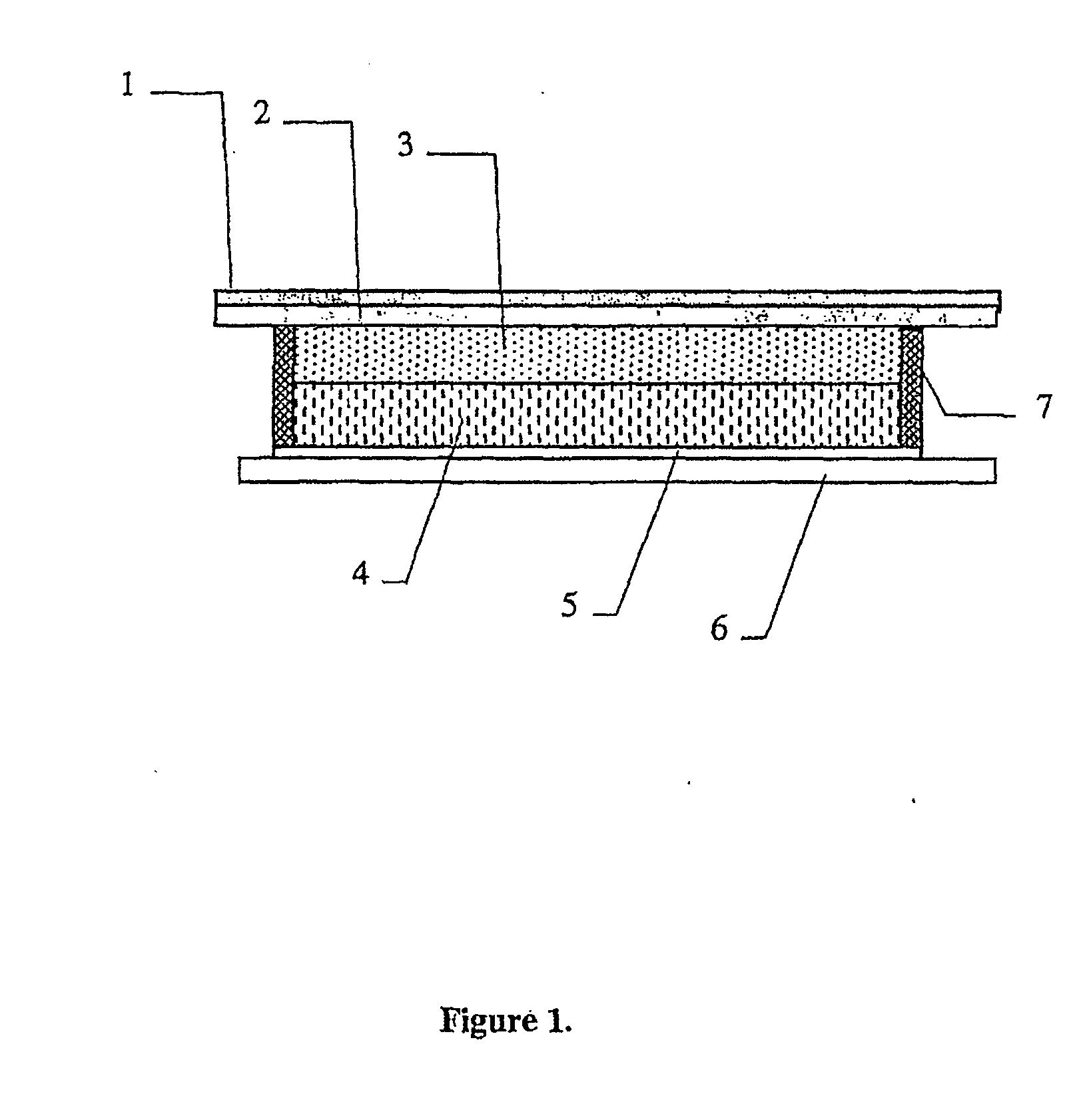
[0032]FIG. 1 is an enlarged cross sectional view of a PEC device formed in accordance with one example of the invention.

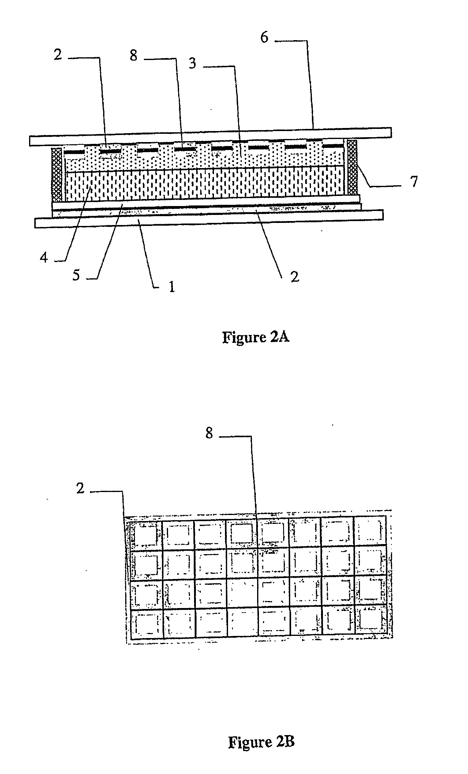
[0033]FIG. 2A is an enlarged cross sectional of a PEC device formed in accordance with another example of the invention.

[0034]FIG. 2B is a diagrammatic view of a stainless steel mesh protected by a TiN coating.

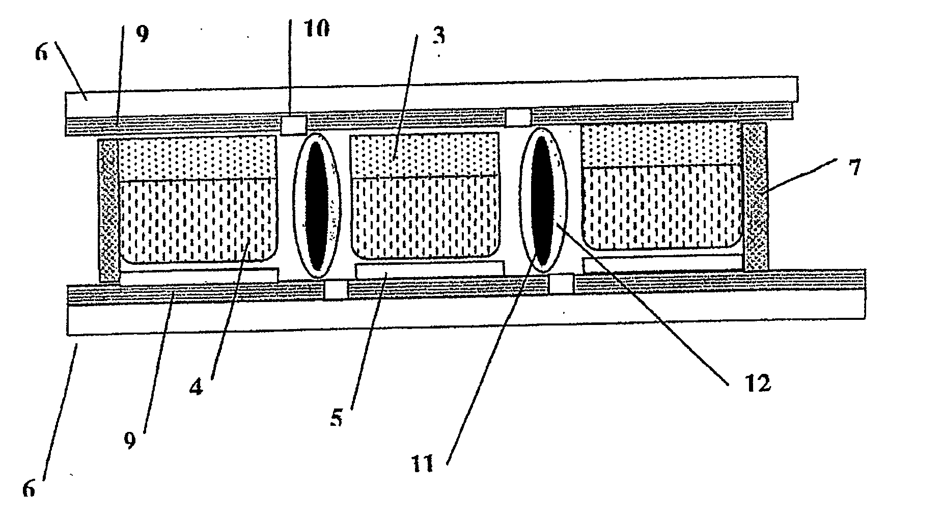
[0035]FIG. 3 is an enlarged cross sectional of a PEC device formed in accordance with further example of the invention.

[0036] Referring to FIG. 1 the working electrode substrate comprises Stainless Steel foil 1 protected by TiN coating 2. Working electrode 3 (dye sensitised TiO2) formed on TiN coating (3 microns thick, filtered plasma deposition). The counter electrode 5 (thin dispersed Pt catalytic layer) of the dev...


PUM

PropertyMeasurementUnit
thickaaaaaaaaaa
transparentaaaaaaaaaa
electrical currentaaaaaaaaaa

Abstract

A photoelectrochemical (PEC) device comprising two substrates, wherein: at least one substrates is transparent and coated with Transparent Electronic Conductor (TEC); a working electrode comprising dye sensitised porous semiconductor is formed on one substrate; a counter electrode comprising catalytic layer is formed on another substrate; electrolyte is placed between the two substrates; metallic conductor are utilized to conduct electrical current within and from the device; a protective layer of non-metallic material, with sufficient electrical conductivity to enable viable electrical output from the PEC device, is used to protect the metallic conductors from the electrolyte of the device.

Description

[0001] This application is a national stage completion of PCT / AU2004 / 000590 filed May 5, 2004 which claims priority from Australian Application Serial No. 2003902117 filed May 5, 2003. TECHNICAL FIELD [0002] This invention relates to photovoltaic (PV) devices and more particularly, but not exclusively, to photoelectrochemical photovoltaic devices. [0003] Further, this invention relates to methods of manufacturing such devices. BACKGROUND TO THE INVENTION [0004] A variety of photovoltaic devices are available for conversion of energy of electromagnetic radiation to electrical energy. These include a conventional solid-state devices (see M. Green Third generation photovoltaics: concepts for high efficiency at low cost, The Electrochemical Society Proceedings, Vol. 2001-10, p. 3-18) and more recently developed photoelectrochemical (PEC) devices [0005] Examples of the PEC cells of the type concerned are disclosed in the following US patents: [0006] U.S. Pat. No. 4,927,721, Photoelectroc...

Claims


Application Information

Patent Timeline
Patent Type & Authority Applications(United States)
IPC IPC(8): C25D17/00
CPCH01G9/2031Y02E10/542H01G9/2081
Inventor TULLOCH, GAVIN EDMUNDSKRYABIN, IGOR LVOVICH
Owner DYESOL IND
Why Eureka
Try Eureka