Increasing fill-factor on pixelated sensors

a technology of pixelated sensors and fill-factors, applied in the field of digital imaging systems, can solve the problems of difficult to achieve 100% fill-factor, process generally does not allow a large fill-factor, and difficulty in precise manufacture, so as to improve the fill-factor performance, increase the fill-factor, and preserve the resolution

Inactive Publication Date: 2006-11-02
CARTLIDGE ANDREW G +3
View PDF28 Cites 34 Cited by
  • Summary
  • Abstract
  • Description
  • Claims
  • Application Information

AI Technical Summary

Benefits of technology

[0010] In yet another aspect, a holographic diffuser, for example, is placed in proximity of a sensor array having a plurality of pixels (e.g., CMOS array, CCD array, and so forth) such that the diffuser creates a virtual point source with a diffusion angle such that a substantially-sharp point (e.g., infinitely-sharp point) present on the diffuser is then diffused or spread to cover about one pixel pitch which provides coherent spatial coupling between active and inactive areas of the sensor array. Thus, any information that may have been lost in the spaces between pixels is spread out across inactive or “deadzone” in order to fall on the active portions of the pixels. In other words, the deadzone is effectively r

Problems solved by technology

In general, it is very difficult to achieve 100% fill-factor, and in some cases, the array process generally does not allow a large fill-factor such as is the case with CMOS sensor technology, for example.
Moreover, lenslet processes by nature pose numero

Method used


Image

  • Increasing fill-factor on pixelated sensors
  • Increasing fill-factor on pixelated sensors
  • Increasing fill-factor on pixelated sensors

Examples


Embodiment Construction

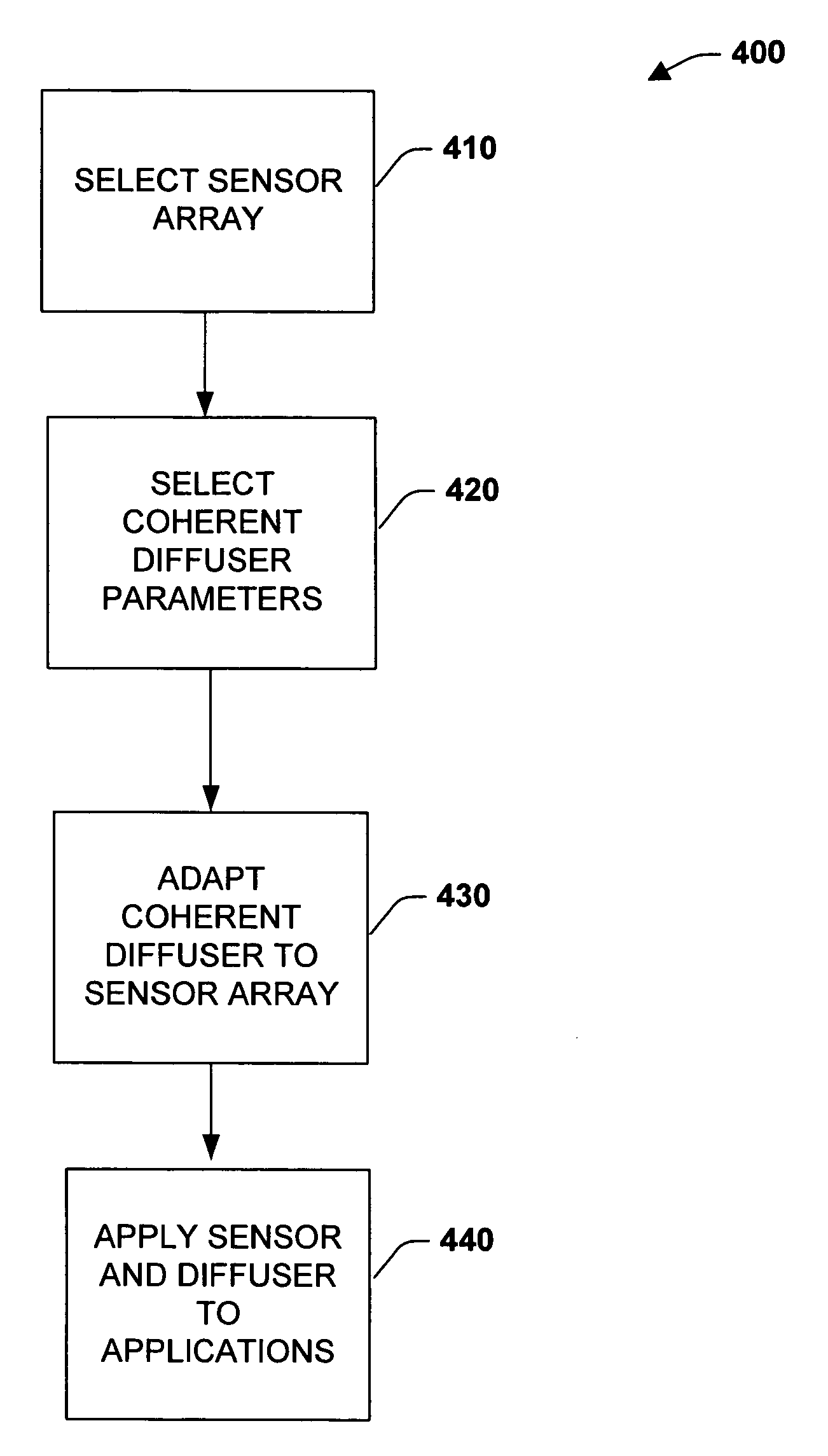
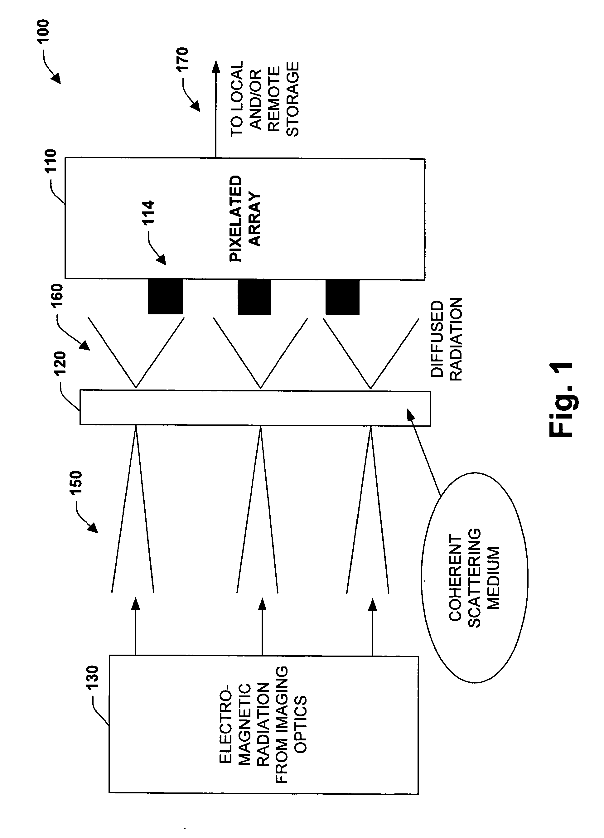
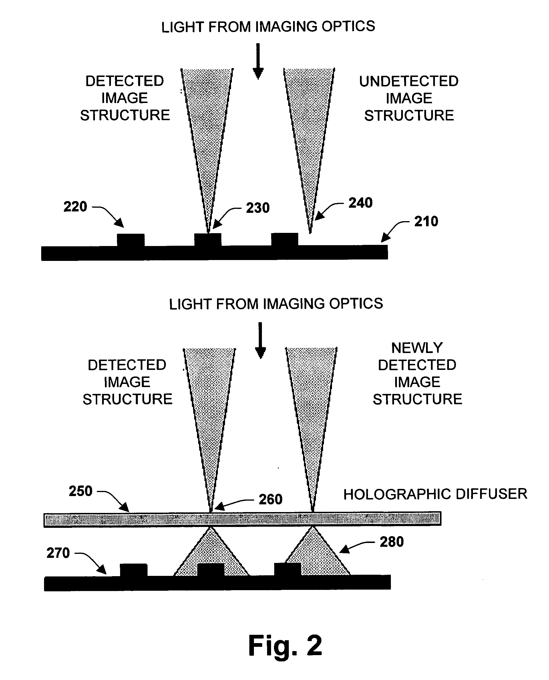
[0022] Disclosed are systems, devices, and methodologies that facilitate increasing the effective fill-factor of digital sensors. In general, fill-factor relates to the active area or photosensor region of the sensor with respect to the deadzone / inactive area or space between pixels on the array. By increasing the effective fill-factor, transmission of increased / maximum amount of optical information to the active portions of the sensor is achieved while mitigating information loss between pixels on the sensor. In one aspect, an image detector system is provided. The system contains a coherent scattering medium and a pixelated sensor that is responsive to electromagnetic radiation such as visible light, for example. The coherent scattering medium diffuses the electromagnetic radiation with respect to the pixelated sensor in order to increase the effective fill-factor of the sensor. In one embodiment, the sensor system does not contain conventional lenslets, conventionally used to add...


PUM


Abstract

Disclosed are systems, devices, and methodologies that facilitate increasing the effective fill-factor of digital sensors. In general, fill-factor relates to the active area or photosensor region of the sensor with respect to the inactive area/deadzone or space between pixels. By increasing the effective fill-factor, transmission of optical information is increased to the sensor while mitigating information loss between pixels. A digital camera may contain a sensor that is responsive to electromagnetic radiation and a coherent scattering medium between the sensor and a lens that diffuses the electromagnetic radiation with respect to the sensor in order to increase the effective fill-factor.

Description

TECHNICAL FIELD [0001] The subject invention relates generally to digital imaging systems, and more particularly to systems and methods with improved sensor performance and design by maximizing the amount of information collected by the sensor. BACKGROUND OF THE INVENTION [0002] One area of concern to sensor array manufacturers is that of ensuring that the active area of their respective products (the pixel) covers the maximum amount of area such that there are substantially no gaps or minimal gaps between pixels. This amount of coverage is usually described as a percentage “fill-factor” and is computed as follows: fill-factor %=(pixel-pixel area) / (pixel active area)*100. In general, it is very difficult to achieve 100% fill-factor, and in some cases, the array process generally does not allow a large fill-factor such as is the case with CMOS sensor technology, for example. There are two primary reasons for achieving the goal of a high fill-factor which include: [0003] 1) To facilit...

Claims


Application Information

Patent Timeline
IPC IPC(8): H04N9/04
CPCH04N5/2254G02B5/021
Inventor CARTLIDGE, ANDREW G.
Owner CARTLIDGE ANDREW G
Why Eureka
Try Eureka