Antirotation tool holder and cutting insert

a tool holder and anti-rotation technology, applied in the field of material cutting tools, can solve the problems of reducing the number of potential applications of carbide tools, requiring replacement of carbide inserts with coated surfaces, and reducing the life of inserts in machining operations,

Active Publication Date: 2006-11-02
KENNAMETAL INC
View PDF17 Cites 45 Cited by
  • Summary
  • Abstract
  • Description
  • Claims
  • Application Information

AI Technical Summary

Benefits of technology

[0026] The cutting insert may be manufactured using a tangential machining method. The method includes tangentially machining at least one antirotation stop and an insert pocket in the tool holder, wherein the antirotation stop comprises at least two substantially planar surfaces. The method may further comprise milling a top surface of the pocket with a ball mill. The tangential method allows forming more pockets per a diameter of the tool holder than an axial machining method.

Problems solved by technology

Additionally, the brazed connection between the carbide insert and the holder could only withstand a limited range of operating temperature, thereby reducing the number of potential applications for the carbide tool.
Additionally, carbide inserts which with coated surfaces could not be resharpened and had to be replaced.
There may be a number of problems, however, in using a round shape inserts in a tool holder for metal machining, in particular in milling operations.
Typical problems for machining with round inserts include inconsistent insert life in machining operations due to an imprecise indexing mechanism compared to square or diamond shape inserts, insecure clamping and positioning of a round inserts since no straight edge is available for indexing, cutting edge chipping may also result from rotation of a round shape insert in the pocket of the cutting tool holder, as well as other reasons.
In addition, the limited contact provided by the polygonal pattern-based design of these inserts may result in one-point contact between the edges of the insert facets and the flat wall of the pocket, which can result in localized chipping or cracking of the insert over time.
There are several disadvantages and limitations in the mechanism described in U.S. Pat. No. 6,238,133, these disadvantages are primarily due to the complexity of the curved and oblique 3-dimensional surfaces in the pocket.
Specifically, first, the complementarily-shaped oblique geometry can require complex machining procedures in the manufacturing of the insert and the corresponding pocket to ensure the necessary geometric and dimensional accuracy required to keep the desired functionality at the contact interface between the insert and the pocket.
Second, the curved and oblique 3-dimensional surface limits the manufacturing methods for the pocket to an axial machining method along the pocket axis.
Third, as a result of the manufacturing limitations of the complex geometry of the tool holder, it further limits number of pockets, thus the number of teeth, in a milling cutter.
If the milling cutter has too few teeth, one tooth will lose contact with the workpiece prior to the next tooth is engaging the workplace.
This will lead to vibration and chatter resulting in poor finishing, dimensional inaccuracies, and excessive tool wear.

Method used


Image

  • Antirotation tool holder and cutting insert
  • Antirotation tool holder and cutting insert
  • Antirotation tool holder and cutting insert

Examples


Embodiment Construction

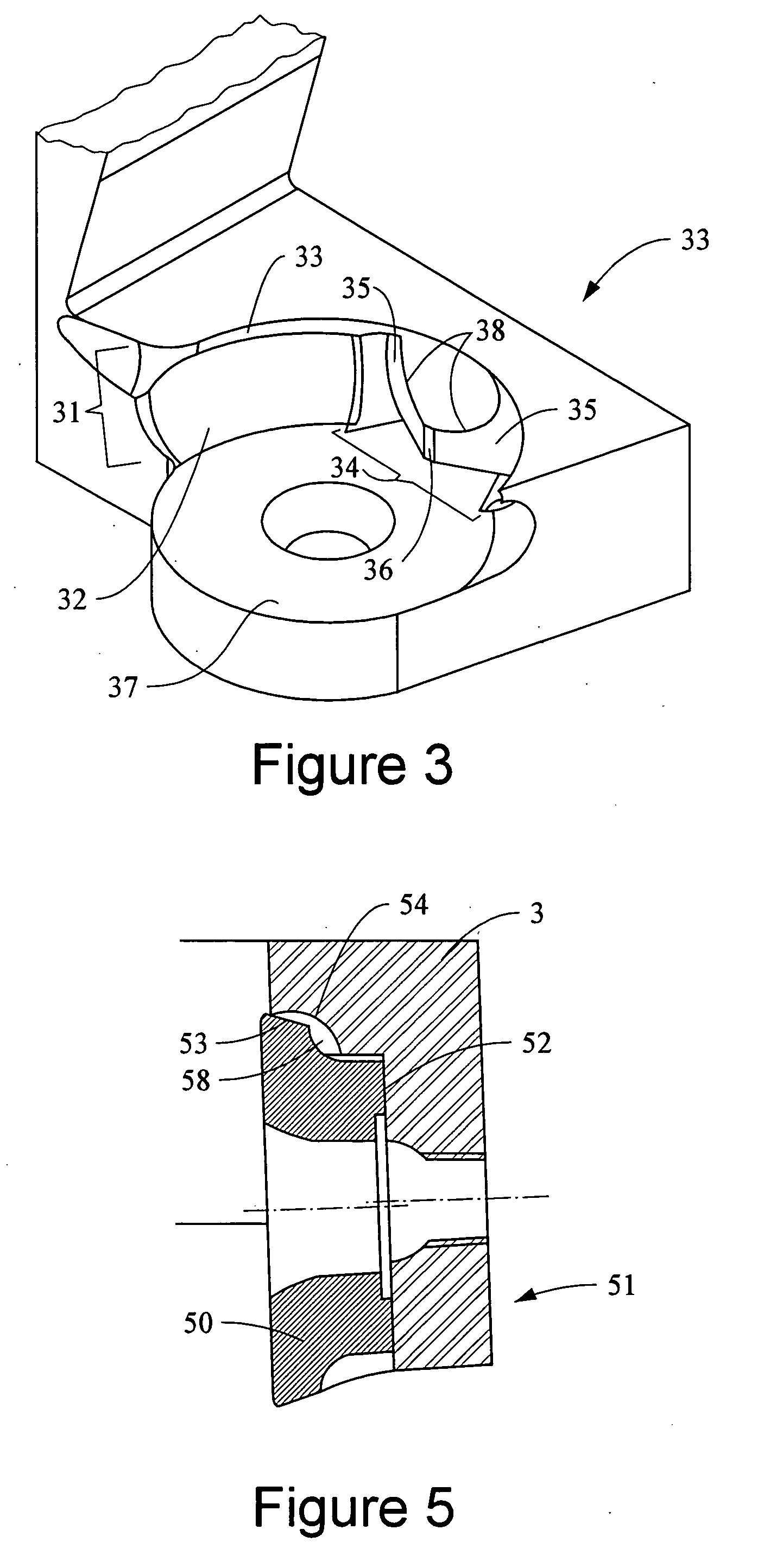
[0027] Embodiments of the tool holder includes at least one insert pocket. Each insert pocket comprises a bottom surface and a side surface, and at least one antirotation stop protruding from the bottom surface, wherein the antirotation stop comprises at least two substantially planar surfaces. The tool holder may be used for any machining operation such as, but not limited to, milling, turning, boring, planing, shaping, and reaming.

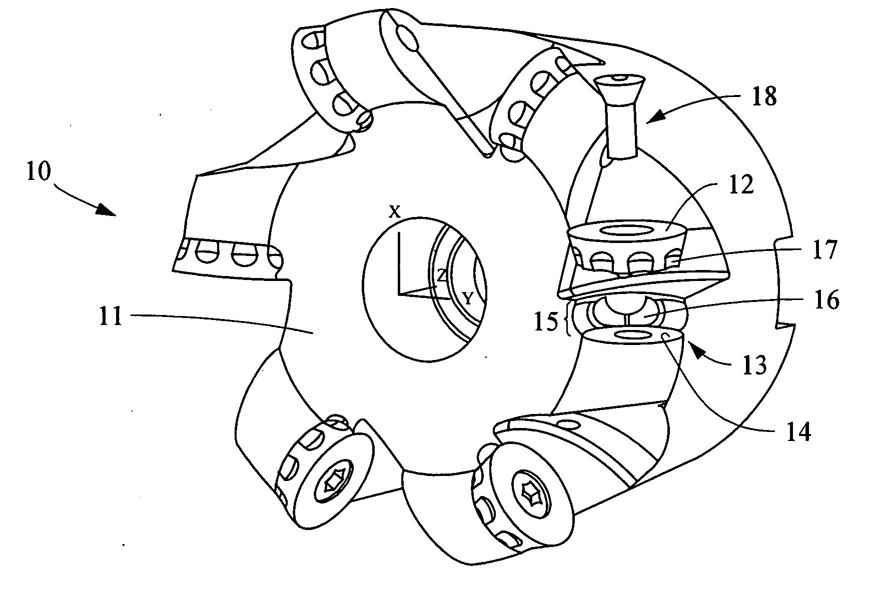
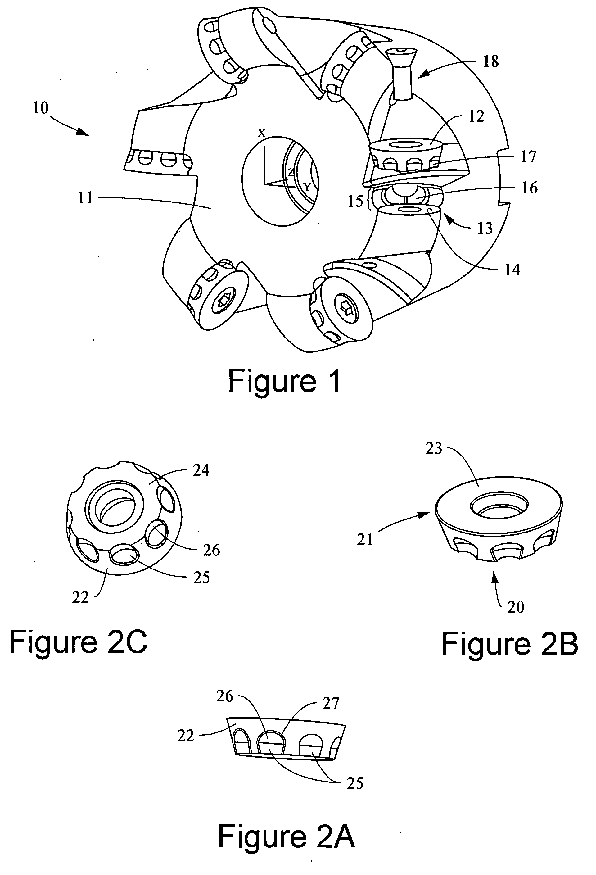
[0028] An embodiment of the tool holder may be a milling cutter tool 10 for an indexable cutting insert, such as shown in FIG. 1. The embodiment of the tool holder in FIG. 1 includes a tool body 11 having six (6) pockets 13 for receiving six (6) indexable round shaped cutting inserts 12. The round shaped cutting inserts 12 may be secured in pockets 13. The pocket 13 of this embodiment of the tool holder comprises a bottom surface 14 and a side wall 15. An antirotation stop 16 protrudes from the side wall 15. The antirotation stop 16 at least partially e...


PUM

PropertyMeasurementUnit
shapeaaaaaaaaaa
cylindrical shapeaaaaaaaaaa
rotationaaaaaaaaaa

Abstract

The present invention relates to embodiments of a cutting tool holder having at least one insert pocket, wherein at least one insert pocket comprises a side surface and at least one antirotation stop protruding from the side surface. The antirotation stop may comprise at least two substantially planar surfaces. In certain embodiments, the cutting tool holder may have a pocket which comprises a bottom surface and an antirotation stop having three substantially planar surfaces that are substantially perpendicular to the bottom surface. The antirotation stop may be integral to the tool holder or may be produced separately and attached, either permanently or temporarily, to the tool holder. Embodiments may further comprise additional antirotation stops if desired by the machining application. In one embodiment, the cutting tool holder includes an insert pocket in the tool holder and at least one antirotation stop protruding from at least one of a side wall and the bottom surface of the insert pocket, wherein the antirotation stop comprises at least two substantially planar surfaces. A cutting insert may be secured in the tool holder, wherein the cutting insert has a recess having a shape that is non-complementary to the shape of the antirotation stop and may be made from tungsten based carbide or cermet.

Description

TECHNICAL FIELD AND INDUSTRIAL APPLICABILITY OF THE INVENTION [0001] The present invention relates to material cutting tools. The present invention more particularly relates to tool holders and cutting inserts. The tool holder and cutting inserts of the present invention comprise an antirotation stop to prevent rotation of the insert while secured in an insert pocket of the tool holder. BACKGROUND OF THE INVENTION [0002] Early carbide cutting tools were typically carbide blanks brazed to steel holders. The blank would be resharpened by grinding. Clearance angles, cutting point radii, and other features could also be ground into the tools to suit a particular cutting operation. Although these early carbide cutting tools provide significant productivity increases over previous tools, certain disadvantages became apparent. Regrinding to sharpen the dulled tool would change the size and shape of the cutting insert. This would require an adjustment of the relationship between the cutting...

Claims


Application Information

Patent Timeline
Patent Type & Authority Applications(United States)
IPC IPC(8): B23C3/36B23C5/22
CPCB23C5/06Y10T409/303808B23C2200/045B23C2200/0466B23C2200/125B23C2200/164B23C2200/168B23C2210/168Y10T407/1936Y10T407/20Y10T82/10Y10T407/2202Y10T407/1944Y10T407/1934Y10T407/192Y10T407/235Y10T407/2274Y10T407/22Y10T407/23Y10T407/2272B23C5/2221Y10T407/1924B23C5/2213B23C5/22B23C5/10B23C5/20
Inventor DUFOUR, JEAN-LUCFANG, X. DANIELWILLS, DAVID J.
Owner KENNAMETAL INC
Why Eureka
Try Eureka