
Diesel particulate filter

a technology of particulate filter and diesel, which is applied in the direction of filtration separation, physical/chemical process catalyst, separation process, etc., can solve the problems of low particulate burning rate of cezr mixed oxide, and tendency to be particularly prominent, so as to increase the particulate burning rate

Inactive Publication Date: 2006-11-02
MAZDA MOTOR CORP
View PDF9 Cites 23 Cited by
  • Summary
  • Abstract
  • Description
  • Claims
  • Application Information

AI Technical Summary

Benefits of technology

[0012] As a result of the inventors' experiments and studies on the relation between the composition and the particulate burning rate of Ce-based mixed oxide acting as an oxygen storage component, the inventors have found that CO in the exhaust gas becomes easy to oxidize at a particular composition of the mixed oxide and the reaction heat of the oxidation promotes the burning of particulates and provides prompt burning of particulates even at a small or zero amount of catalytic metal, thereby completing the present invention.
[0046] In this solution, La is used as the rare earth element R in the above CePrR-type mixed oxide. In this case, if the mixed oxide has a La / (Ce+Pr+La) mole ratio of 13% or less, this is advantageous in increasing the particulate burning rate.

Problems solved by technology

However, ceria and Ce−Zr mixed oxides are low in the burning rate of particulates when they carry no catalytic metal and conventional mixed oxides of Ce and another rare earth element do not always have high particulate burning rates.
This tendency is particularly pronounced when a NOx trap catalyst is disposed in the exhaust flow upstream of the DPF, because NO2 cannot be used for oxidation of particulates.
If, as in such cases, particulates in the DPF cannot be promptly burned off, this increases the back pressure of the engine, resulting in deteriorated fuel economy.
Therefore, it is a reality that the amount of catalytic metal such as Pt cannot help but be increased.
In this case, however, the catalyst cannot obtain sufficient thermal resistance because of the above sintering problem.
Further, even if the technique is employed in which an oxidation catalyst is disposed upstream of the DPF to supply fuel (HC constituents) to the oxidation catalyst and thereby raise the exhaust gas temperature, the fuel supply deteriorates fuel economy.

Method used


Image

  • Diesel particulate filter
  • Diesel particulate filter
  • Diesel particulate filter

Examples


Embodiment Construction

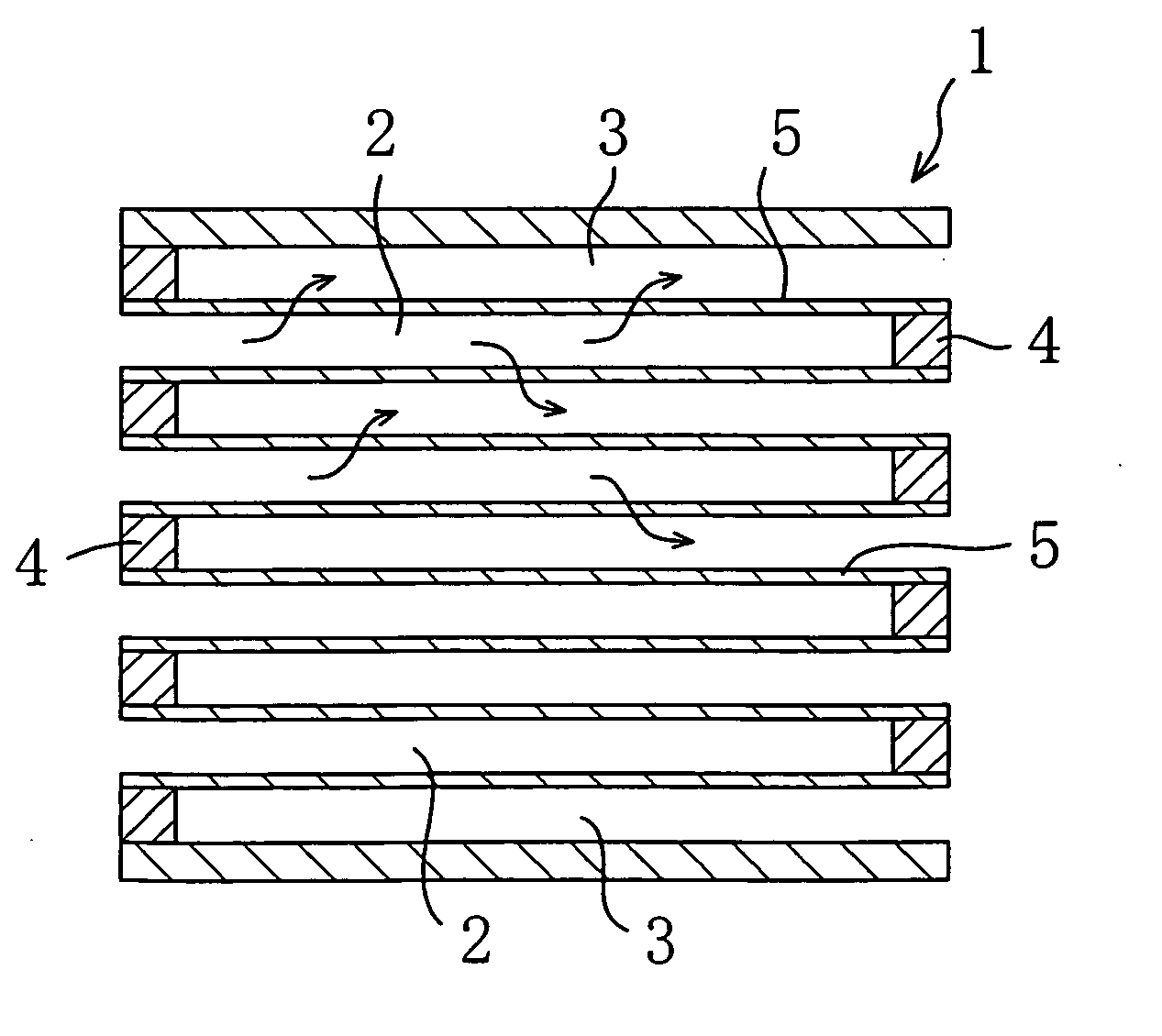
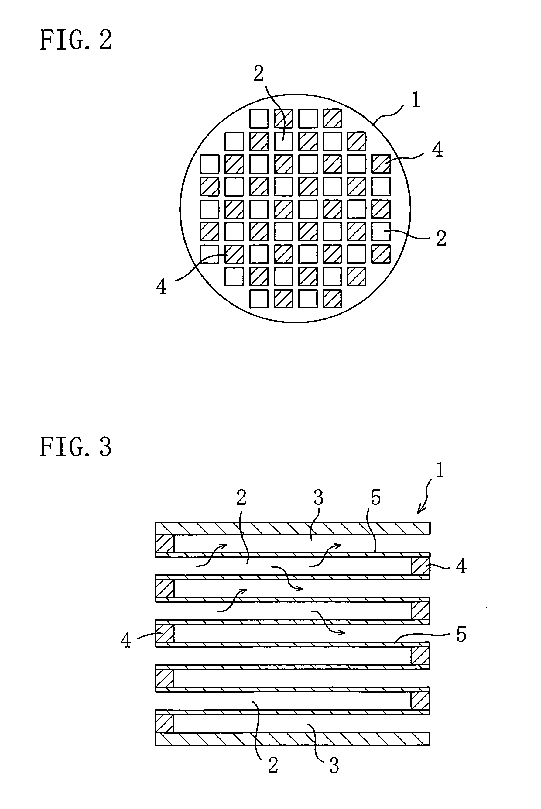
[0056] An embodiment of the present invention will be described in detail below with reference to the drawings.

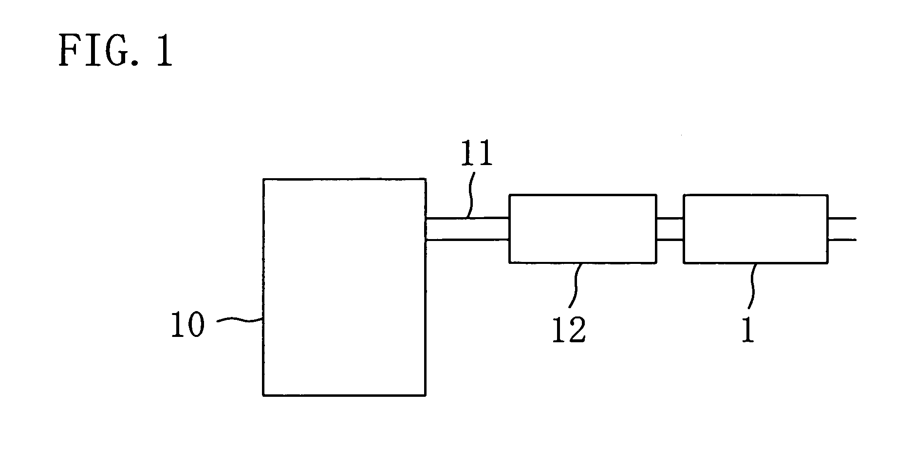
[0057] In FIG. 1, the reference numeral 1 denotes a DPF disposed in an exhaust passage 11 of a diesel engine 10. An upstream catalyst 12 is disposed in part of the exhaust passage 11 located upstream of the DPF 1 in the flow direction of exhaust gas. A NOx trap catalyst, an oxidation catalyst or both can be disposed as the upstream catalyst 12.

[0058] The NOx trap catalyst is obtained by carrying, on a support material such as active alumina, a NOx storage component (such as an alkali earth metal, typically Ba, or an alkali metal) for absorbing NOx in the exhaust gas at high oxygen concentrations in the exhaust gas (at lean air-fuel ratios) and a catalytic metal, such as Pt, for reducing NOx released from the NOx storage component when the oxygen concentration in the exhaust gas drops (at stoichiometric or rich air-fuel ratios).

[0059] The oxidation catalyst is obtained by...


PUM

PropertyMeasurementUnit
temperatureaaaaaaaaaa
mass %aaaaaaaaaa
temperatureaaaaaaaaaa

Abstract

The present invention is intended to configure a diesel particulate filter to allow the burning rate of particulates to increase even with a small amount of catalytic metal or even without using any catalytic metal. In the diesel particulate filter, walls forming exhaust gas channels in a filter body on which the particulates are trapped are coated with a catalyst layer for promoting the burning of the trapped particulates. The catalyst layer contains a mixed oxide in which Ce, Zr and a rare earth element R other than Ce are contained in a Ce / (Ce+Zr) mole ratio between 10% and 90% both inclusive or between 20% exclusive and 80% inclusive.

Description

CROSS-REFERENCES TO RELATED APPLICATIONS [0001] This application claims priority under 35 USC 119 to Japanese Patent Applications Nos. 2005-130018 and 2006-8592, the entire contents of both of which are incorporated herein by reference. BACKGROUND OF THE INVENTION [0002] (a) Field of the Invention [0003] This invention relates to diesel particulate filters. [0004] (b) Description of the Related Art [0005] Active developments have been made recently in techniques for trapping particulates (fine particulate matter, especially carbon particulates) exhausted from a diesel engine on a filter and burning off the trapped particulates. [0006] A known typical example of the techniques is a technique in which an oxidation catalyst is disposed in an exhaust flow upstream of a diesel particulate filter (hereinafter, referred to as a DPF) and HC constituents in fuel or the like are supplied to the oxidation catalyst. Specifically, the oxidation catalyst burns HC constituents to raise the tempera...

Claims


Application Information

Patent Timeline
Patent Type & Authority Applications(United States)
IPC IPC(8): B01D53/34B01J23/10
CPCB01D53/944B01J35/04B01J23/63B01J23/10B01J35/57B01J35/56
Inventor HARADA, KOICHIROTSUSHIO, YOSHINORITAKAMI, AKIHIDE
Owner MAZDA MOTOR CORP
Learn More