Energy delivery devices and methods

a technology of energy delivery and energy storage, applied in the field of energy delivery devices and methods, can solve the problems of difficult breathing of asthma sufferers, difficulty in patient compliance with pharmacologic management, and high doses of corticosteroid anti-inflammatory drugs, etc., and achieve the effect of better distinction

Active Publication Date: 2006-11-02
BOSTON SCI SCIMED INC
View PDF103 Cites 103 Cited by
  • Summary
  • Abstract
  • Description
  • Claims
  • Application Information

AI Technical Summary

Benefits of technology

[0026] In addition, certain wavelengths may afford separation from red and orange (e.g., 590 nm, 570 nm, 470 nm or yellow, green, and blue.) These colors may offer better distinction when used in airways.

Problems solved by technology

Asthma is a disease in which (i) bronchoconstriction, (ii) excessive mucus production, and (iii) inflammation and swelling of airways occur, causing widespread but variable airflow obstruction thereby making it difficult for the asthma sufferer to breathe.
High doses of corticosteroid anti-inflammatory drugs can have serious side effects that require careful management.
The difficulty involved in patient compliance with pharmacologic management and the difficulty of avoiding stimulus that triggers asthma are common barriers to successful asthma management.
Current management techniques are neither completely successful nor free from side effects.
Tortuous anatomy also poses challenges when the treatment device requires mechanical actuation of the treatment portion (e.g., expansion of a treatment element at a remote site).
In particular, attempting to actuate a member may be difficult in view of the fact that the force applied at the operator's hand-piece must translate to the distal end of the device.
Accordingly, when energy or force is applied to move two polymers against each other, a significant part of friction between the polymers is the energy loss through inelastic hysteresis.
In addition, adhesion between polymers also plays a significant part in the friction between such polymers.
Yet, variances in the construction of the treatment device may hinder proper alignment or orientation of the device.
However, in this case, design or manufacturing variances may tend to produce a device where the angle between basket elements is not uniform.
This problem tends to be exacerbated after repeated actuation of the device and / or navigating the device through tortuous anatomy when the imperfections of the device become worsened through plastic deformation of the individual components.
Experience demonstrates that once a member becomes predisposed to splaying (i.e., not maintaining the desired angular separation from an adjacent element), or inverting (i.e., buckling inward instead of deploying outward), the problem is unlikely to resolve itself without requiring attention by the operator.
This interruption tends to increase the time of the treatment session.
However, the tortuous nature of the airways was found to cause significant bending and / or flexure of the distal end of the device.
For many treatment devices, the distortion of the energy transfer elements might cause variability in the treatment effect.
This directly affects the extent to which the tissue is heated.
In any number of cases, variability of the energy transfer / tissue interface causes variability in treatment results.
The consequential risks range from an ineffective treatment to the possibility of patient injury.
Therefore, distortion of the transfer element or elements increases the procedure time when the practitioner spends an inordinate amount of time adjusting a device to compensate for or avoid such distortion.
Such action becomes increasingly problematic in those cases where proper patient management limits the time available for the procedure.
For example, if a patient requires an increasing amount of medication (e.g., sedatives or anesthesia) to remain under continued control for performance of the procedure, then a medical practitioner may limit the procedure time rather than risk overmedicating the patient.
Subsequently, increasing the number of sessions poses additional consequences on the part of the patient in cost, the residual effects of any medication, adverse effects of the non-therapeutic portion of the procedure, etc.
Alternatively, or in combination, the medical practitioner may advance a device out of the bronchoscope into distal airways where visualization is difficult because the scope's light source is insufficient or blocked.

Method used


Image

  • Energy delivery devices and methods
  • Energy delivery devices and methods
  • Energy delivery devices and methods

Examples


Embodiment Construction

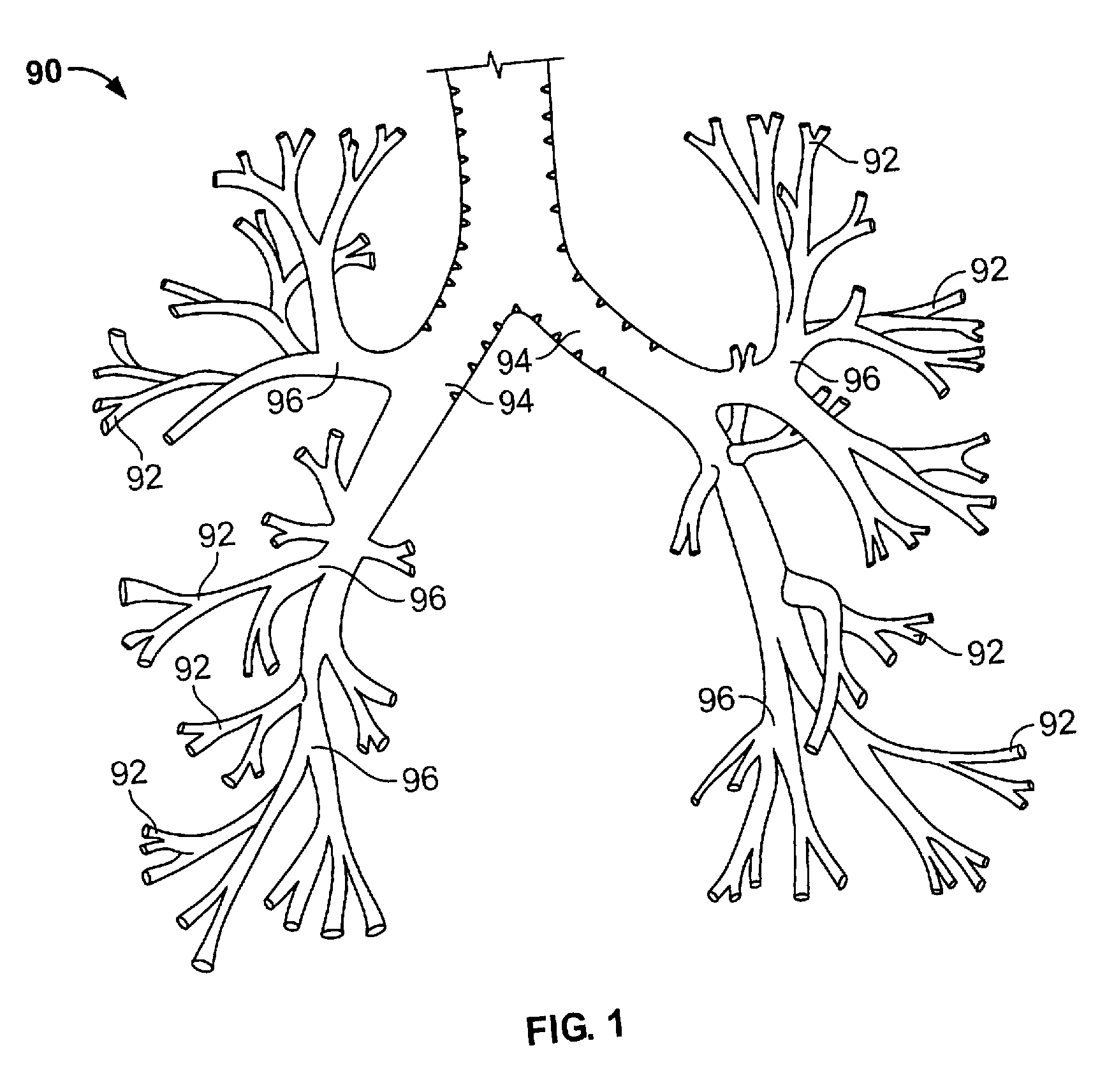
[0043] It is understood that the examples below discuss uses in the airways of the lungs. However, unless specifically noted, the invention is not limited to use in the lung. Instead, the invention may have applicability in various parts of the body. Moreover, the invention may be used in various procedures where the benefits of the device are desired.

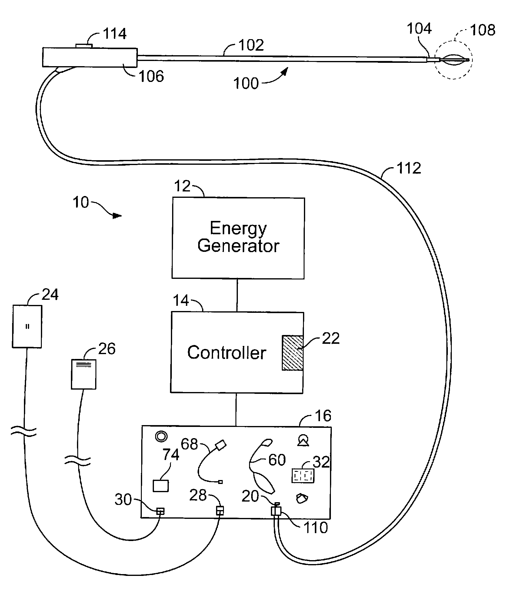
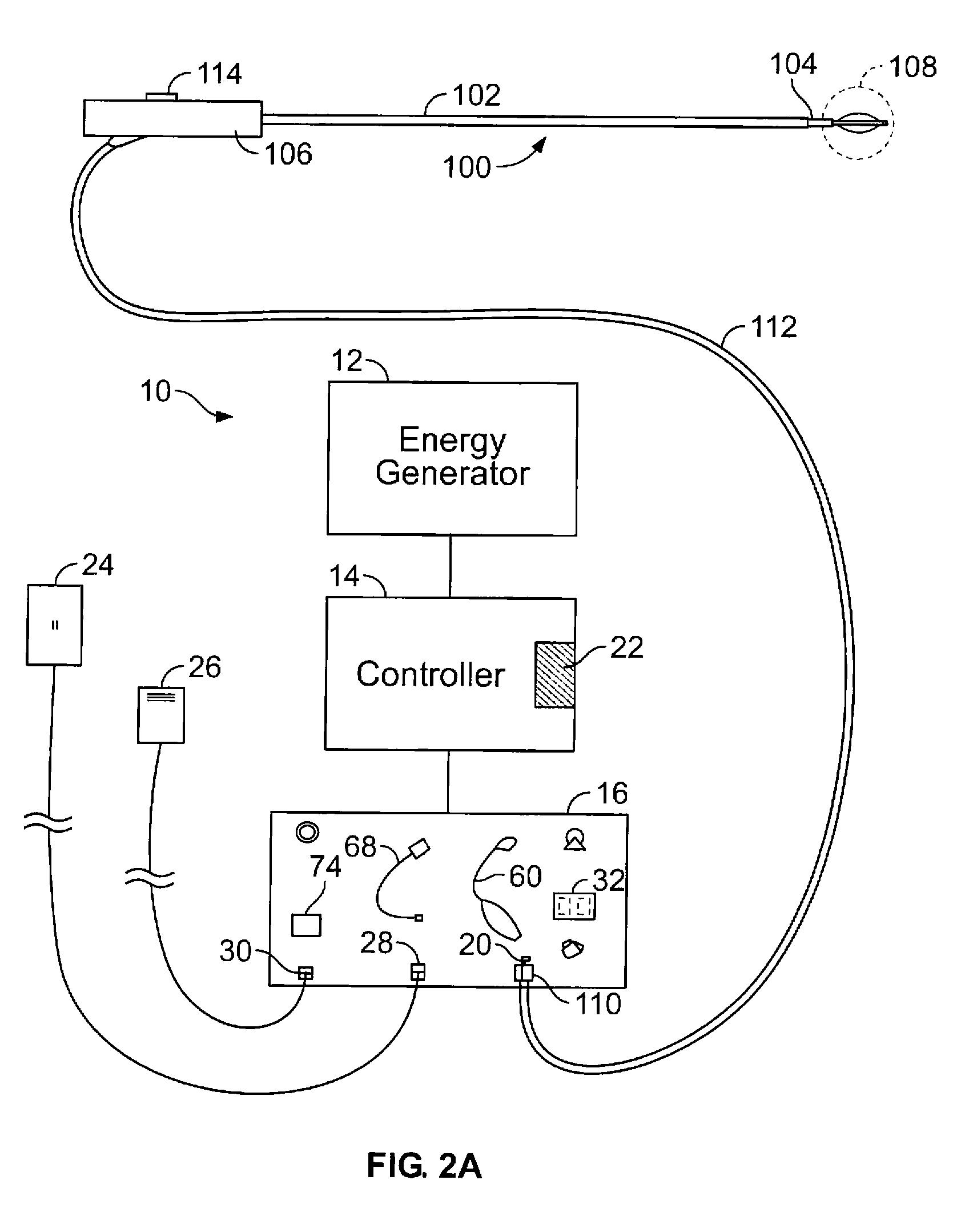
[0044]FIG. 2A shows a schematic diagram of one example of a system 10 for delivering therapeutic energy to tissue of a patient for use with the device described herein. The illustrated variation shows, the system 10 having a power supply (e.g., consisting of an energy generator 12, a controller 14 coupled to the energy generator, a user interface surface 16 in communication with the controller 14). It is noted that the device may be used with a variety of systems (having the same or different components). For example, although variations of the device shall be described as RF energy delivery devices, variations of the device may inclu...


PUM


Abstract

This relates to methods and devices for improving treatment to a wall, a cavity or passageway with a medical device when used in tortuous anatomy.

Description

CROSS-REFERENCE TO RELATED APPLICATIONS [0001] This application is a continuation of PCT Application No. PCT / US2005 / 041243 , filed Nov. 14, 2005, which claims the benefit to U.S. Provisional Patent Application No. 60 / 627,662, filed Nov. 12, 2004 and is a continuation of U.S. patent application Ser. No. 11 / 255,796, filed Oct. 21, 2005, the contents of which are incorporated herein by reference in their entirety.BACKGROUND OF THE INVENTION [0002] Asthma is a disease in which (i) bronchoconstriction, (ii) excessive mucus production, and (iii) inflammation and swelling of airways occur, causing widespread but variable airflow obstruction thereby making it difficult for the asthma sufferer to breathe. Asthma is a chronic disorder, primarily characterized by persistent airway inflammation. However, asthma is further characterized by acute episodes of additional airway narrowing via contraction of hyper-responsive airway smooth muscle. [0003] Asthma is managed pharmacologically by: (1) lon...

Claims


Application Information

Patent Timeline
Patent Type & Authority Applications(United States)
IPC IPC(8): A61B18/18
CPCA61B18/02A61B18/08A61B18/1492A61B19/5202A61B2018/00214A61B2018/00267A61B2018/00541A61B2018/00791A61B2018/00797A61B2018/00821A61N7/022A61B2018/0022A61B90/30
Inventor DANEK, CHRISTOPHER J.KAPLAN, GARY S.WIZEMAN, WILLIAM J.LAUFER, MICHAEL D.
Owner BOSTON SCI SCIMED INC
Why Eureka
Try Eureka