Co-injected pipe fitting

a pipe fitting and co-injected technology, applied in the direction of pipes, pipe connection arrangements, mechanical equipment, etc., can solve the problems of unfavorable pipe fittings, large size of pipe fittings, and high cost of polymer materials, so as to improve the structural characteristics of the fittings and reduce the weight

Inactive Publication Date: 2006-11-09
NIBCO INC
View PDF18 Cites 11 Cited by
  • Summary
  • Abstract
  • Description
  • Claims
  • Application Information

AI Technical Summary

Benefits of technology

[0004] There is a need, therefore, for pipe fittings which can be injection molded and which can employ an inner core which is either inexpensive, lighter in weight, or which has c

Problems solved by technology

The cost of pipe fittings utilizing polymeric materials, such as PVS and ABS, and particularly pipe fittings which are 1- 1/2″ or larger in dia

Method used


Image

  • Co-injected pipe fitting
  • Co-injected pipe fitting
  • Co-injected pipe fitting

Examples


Embodiment Construction

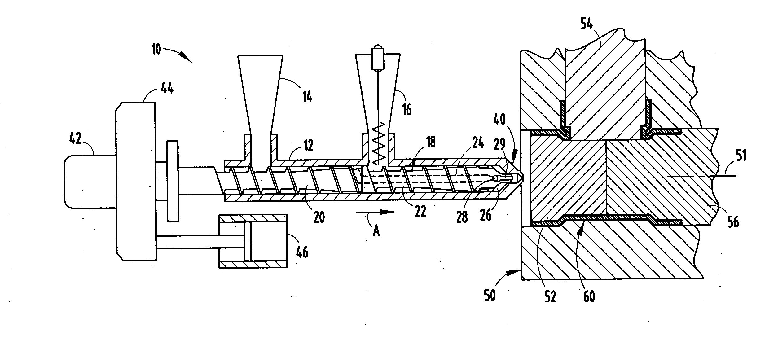
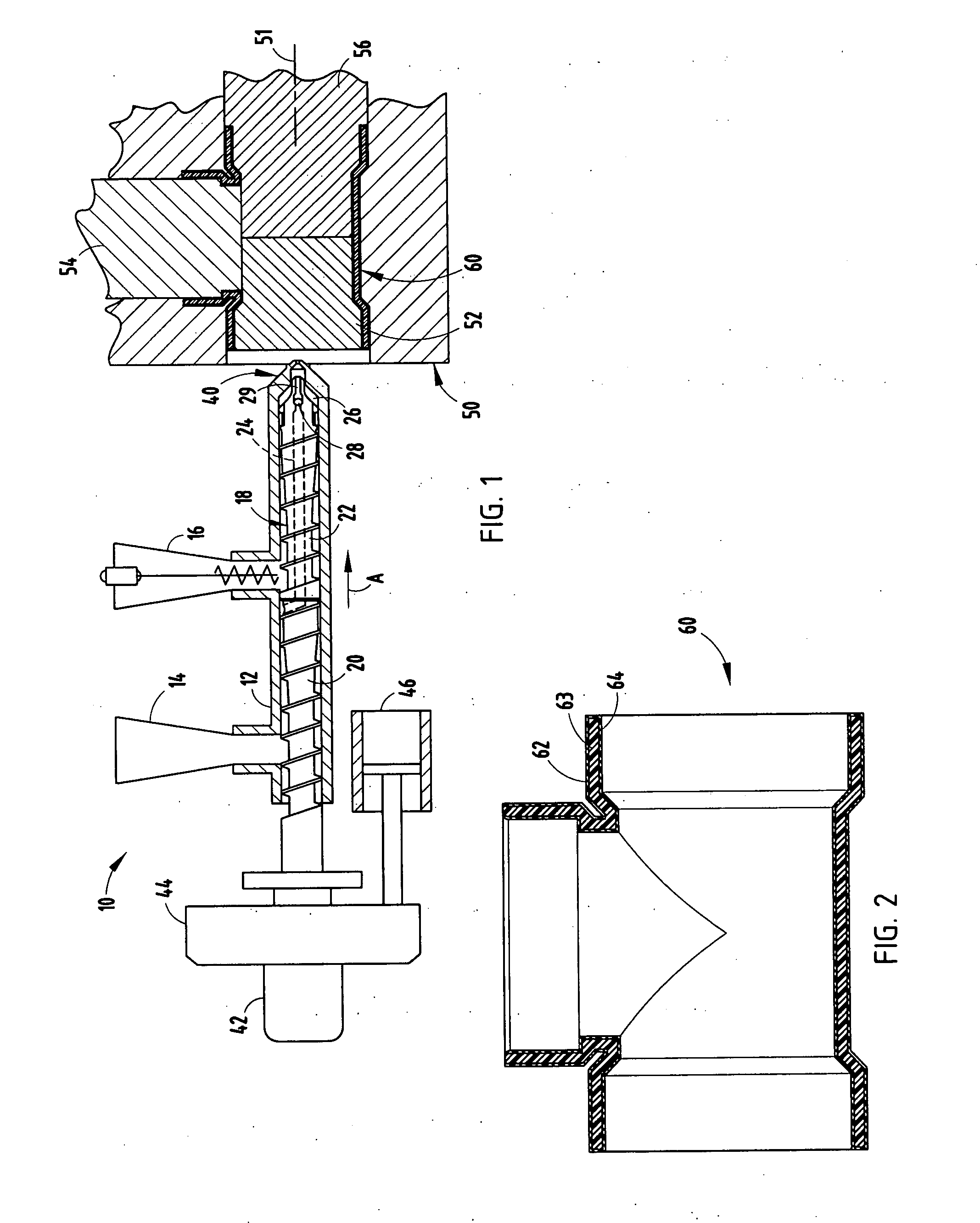
[0013] Referring initially to FIG. 1, there is shown a, schematic view of an injection molding machine 10 which is employed in the co-injection of pipe fittings according to the present invention. The machine is commercially available and manufactured by Spirex Corporation and identified as a Twinshot co-injection design barrel and screw. In FIG. 1, there is shown a schematic diagram of such a machine 10 which includes a barrel 12 with a first feed hopper 14 and a second feed hopper 16. The first feed hopper 14 carries the material which is employed to inject the skin layers of a fitting according to the present invention, while the second feed hopper 16 includes the material which forms the core of the fittings.

[0014] The injector 10 includes a dual feed screw 18 with a first thread flight 20 and a second thread flight 22 for carrying polymeric material from feed hoppers 14 and 16 inside barrel 12 to convert it to a fluid form. A conduit 24 (shown in phantom in FIG. 1) allows the ...


PUM

PropertyMeasurementUnit
Weightaaaaaaaaaa
Thicknessaaaaaaaaaa
Shapeaaaaaaaaaa

Abstract

A co-injected fitting has a core made of recycled or reground PVC and ABS, which is less expensive and to which, in some embodiments, a blowing agent, such as azo and/or sodium bicarbonate, can be added to lower the weight. The fitting includes a skin on opposite sides of the core forming the internal side of the fitting and the external side of the fitting, respectively, in concentric relationship to the inner core. Such fittings may also include a strengthening core material, such as polycarbonate, to provide a stronger pipe fitting which likewise can be co-injection molded.

Description

CROSS-REFERENCE TO RELATED APPLICATIONS [0001] This application claims priority under 35 U.S.C. §119(e) on U.S. Provisional Application No. 60 / 677,036 entitled CO-INJECTED PIPE FITTING, filed on May 3, 2005, by Earl H. Sexton, et al. +the entire disclosure of which is incorporated herein by reference.BACKGROUND OF THE INVENTION [0002] The present invention relates to pipe fittings and particularly pipe fittings which can be injection molded utilizing co-injection of different polymeric materials. [0003] Pipe fittings include elbows, T-s, couplings, and the like, which are employed for transmitting fluids in conduits and coupling conduits in flow systems. The use of thermoplastic materials to injection mold such fittings is well known. The conventional methods of producing composite pipe joints include the use of thermoset materials and multiple production steps resulting in a composite pipe fitting or pipe section comprised of multiple layers of thermoset and / or thermoplastic materi...

Claims


Application Information

Patent Timeline
IPC IPC(8): F16L9/14
CPCB29C44/1228B29C45/1642F16L47/32B29K2105/26B29C45/261
Inventor SEXTON, EARL H.KREZEL, JAMES A.PLETCHER, MICHAEL J.
Owner NIBCO INC
Why Eureka
Try Eureka