Laser sintering process chamber gas curtain window cleansing in a laser sintering system

a laser sintering and process chamber technology, applied in the field of rapid prototyping and manufacturing, can solve the problems of affecting the efficiency of laser sintering, so as to avoid thermal control loss during the laser sintering process, minimize the build-up of chemical by-products, and minimize the effect of chemical by-products

Active Publication Date: 2006-11-09
3D SYST INC
View PDF13 Cites 48 Cited by
  • Summary
  • Abstract
  • Description
  • Claims
  • Application Information

AI Technical Summary

Benefits of technology

[0019] It is an advantage of the present invention that the build-up of film-like coating deposits and frost-like crystalline deposits on the exposed surface of process equipment functional windows is minimized.
[0020] It is another advantage of the present invention that loss of thermal control during the laser sintering process is avoided by use of the inert gas diffuser mounted to process equipment functional windows.
[0021] These and other aspects, features, and advantages are obtained by the discharge orifice from an inert gas diffuser that provides a curtain of velocity controlled, laminar flow, temperature controlled, clean, inert gas parallel to the process chamber exposed surface of process equipment windows with a Reynolds number characteristic of the flow geometry to minimize the build up of chemical by-products during the laser sintering process. BRIEF DESCRIPTION OF THE SEVERAL VIEWS OF THE DRAWING(S)

Problems solved by technology

Especially susceptible to the build-up of these chemical by-products are the process functional equipment glass windows on the interior and ceiling of the process chamber.
The build-up of chemical by-products on process chamber exposed surface of the laser window is especially problematic because over a relatively short period of time the laser power delivered to the powder bed can be attenuated by as much as 50% in areas with film build-up and by as much as 71% in areas with frost-like crystalline build-up.
Other process equipment functional windows within the process chamber that can become obstructed with chemical by-product build-up include the IR sensor window and IR camera window for which any attenuation of the IR signal between the powder part bed and the sensing devices can cause catastrophic loss of thermal control during the laser sintering process.
If a video camera is employed to film the build process, that process functional window can also become obstructed and prevent effective filming from occurring over time.
This chemical by-product build-up has been long recognized as a problem by laser sintering system manufacturers and users.
This approach encountered the same problems as the earlier DTM Corporation approach.
Both approaches were further hampered by the fact that the relatively high flow rate of inert gas.

Method used


Image

  • Laser sintering process chamber gas curtain window cleansing in a laser sintering system
  • Laser sintering process chamber gas curtain window cleansing in a laser sintering system
  • Laser sintering process chamber gas curtain window cleansing in a laser sintering system

Examples


Embodiment Construction

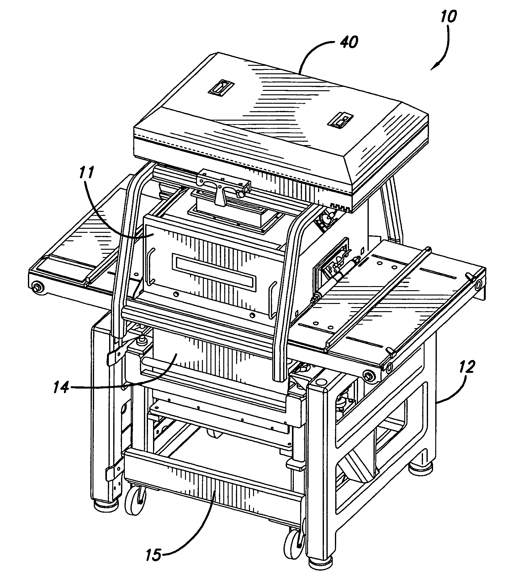
[0027] A laser sintering apparatus or system having a removable build chamber is illustrated in FIG. 1 indicated generally by the numeral 10. The laser sintering system 10 includes a process chamber 11, an associated support housing 12, and a removable build chamber 14 that may be supported by a build carriage 15. The build carriage 15, along with the build chamber 14, may be removably inserted into the support housing 12. In some embodiments, the laser sintering apparatus 10 may include a lifting device (not shown in FIG. 1) that is adapted to move the build chamber 14 between a load position and a build position. As used herein, the term “build position” refers to the position of the build chamber 14 wherein the build platform is properly aligned with the powder bed such that vertical travel of the build platform is substantially perpendicular to the powder bed. In the build position the laser sintering apparatus 10 is ready to build parts. The lifting device can comprise hydrauli...


PUM

PropertyMeasurementUnit
Reynolds numberaaaaaaaaaa
temperatureaaaaaaaaaa

Abstract

An inert gas dispenser for mounting to a process equipment functional window is provided to dispense an inert gas in a laminar flow at an effective velocity across the exposed surface to form a curtain of inert gas across the exposed surface to prevent a build-up of chemical by-product from the powder material during laser sintering. The gas flow rate is characteristic of a flow geometry having a Reynolds number below the turbulent range. The diffuser is used in a laser sintering system.

Description

BACKGROUND OF THE INVENTION [0001] The invention relates generally to a method of rapid prototyping and manufacturing and, more particularly, to laser sintering and the ability to prevent the build up of monomers and oligomers that condense and solidify in the form of films or larger crystals on windows within the process chamber during laser sintering operations. [0002] Rapid prototyping and manufacturing (RP&M) is the name given to a field of technologies that can be used to form three-dimensional objects rapidly and automatically from computer data representing the objects. In general, rapid prototyping and manufacturing techniques build three-dimensional objects, layer-by-layer, from a working medium utilizing sliced data sets representing cross-sections of the object to be formed. Typically an object representation is initially provided by a Computer Aided Design (CAD) system. RP&M techniques are sometimes referred to as solid imaging and include stereolithography, ink jet prin...

Claims


Application Information

Patent Timeline
Patent Type & Authority Applications(United States)
IPC IPC(8): B23K26/00
CPCB29C67/0077B29C64/153B33Y30/00
Inventor PARTANEN, JOUNI P.ZHENG, NINGBISHOP, RAYMOND J.
Owner 3D SYST INC
Why Eureka
Try Eureka