Phase and frequency detection circuits for data communication systems

Active Publication Date: 2006-11-09
REALTEK SEMICON CORP
View PDF2 Cites 30 Cited by
  • Summary
  • Abstract
  • Description
  • Claims
  • Application Information

AI Technical Summary

Benefits of technology

[0014] In one embodiment, the phase detector provides the retiming function as part of its operation to reduce the phase error. The frequency detector can act as an aided phase detector during phase lock to provide finer resolutions of phase difference between the incoming data and the VCO clock. Instead of generating a very narrow pulse for a small phase error as in linear phase detector, different amounts of charge UP / DOWN currents with a fixed pulse width may be fed to the charge-pump circuit depending on the phase difference. Therefore, a much smaller phase error can be achieved.
[0015] Embodiments of the present invention may be implemented as an all digital phase and frequency detector. This makes the PLL system advantageous in sub-micron VLSI technology. Furthermore, the PLL system can be extended to a half-rate clocking scheme. In other words, the VCO clock may be configured to run at one half of the baud rate of the incoming data, making the PLL system applicable to technology with limited bandwidth.
[0016] Some of the inventive aspects of the present invention are enumerated as follows. In a first aspect, the present invention provides a method and apparatus for aligning the phases and determining the frequency difference between the incoming data and the VCO clock. In a second aspect, the present invention provides a method and apparatus for eliminating the need for a lock-in detector. A false-lock detector is provided in some embodiments to detect false-locking. In a third aspect, the present invention provides an aided phase detector for achieving finer resolutions of phase error, thus resulting in a much smaller phase error during phase lock. In a fourth aspect, the present invention provides an all digital phase and frequency detector, which is suitable for very-large-scale-integrated (VLSI) implementations. In a fifth aspect, the present invention allows for a half-rate clocking scheme, which is suitable for high-speed implementations.

Problems solved by technology

A problem with linear phase detectors is that they may not work well at very high-speed data rates because the detector has to generate a very narrow pulse for a small phase error.
Unbalanced loading and delay mismatch can worsen this problem.
Therefore, linear phase detectors suffer from a relatively large phase error.
In a very high-speed link, a slight misalignment can lead to a significant increase of bit error rate.
If not carefully designed, a system employing a quadricorrelator may not function as expected.
This degrades the performance of the PLL system 200.
Unfortunately, the LID 207 may falsely detect an out-of-lock condition and improperly enable the rotational frequency detector output 226.
This causes further PLL performance degradation.

Method used


Image

  • Phase and frequency detection circuits for data communication systems
  • Phase and frequency detection circuits for data communication systems
  • Phase and frequency detection circuits for data communication systems

Examples


Embodiment Construction

[0039] In the present disclosure, numerous specific details are provided, such as examples of electrical circuits, components, and methods, to provide a thorough understanding of embodiments of the invention. Persons of ordinary skill in the art will recognize, however, that the invention can be practiced without one or more of the specific details. In other instances, well-known details are not shown or described to avoid obscuring aspects of the invention.

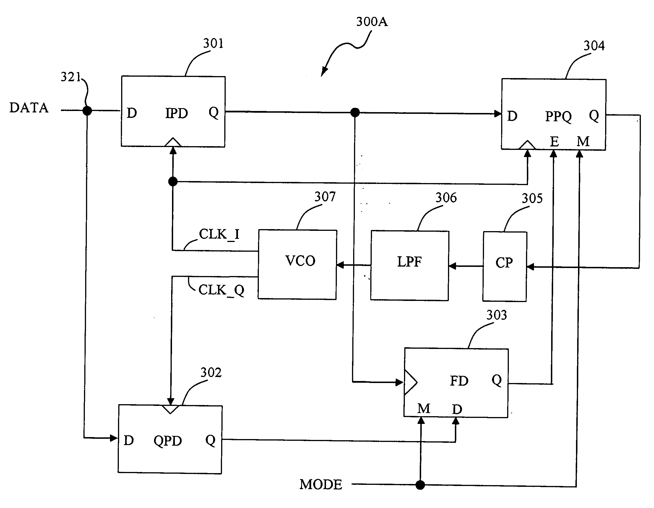
[0040]FIG. 3A shows a block diagram of a PLL system 300A in accordance with an embodiment of the present invention. In the example of FIG. 3A, the PLL system 300A operates at the baud rate of the incoming data, also referred to as “input data” or simply “data”, at a node 321. In one embodiment, the incoming data comprise non-return to zero (NRZ) data. Embodiments of the present invention may also be adapted to work with data encoded using encoding schemes other than NRZ without detracting from the merits of the present invention...


PUM


Abstract

In one embodiment, a phase-locked loop system in a receiver samples received incoming data using a first clock and a second clock that have the same frequency but are out of phase with each other. A first control signal generated by a phase detector is used to control a charge pump, whose output may be filtered to drive a VCO circuit generating the first and second clocks. A frequency detector generates a second control signal based at least on phase relationships between the incoming data and the first and second clocks. A qualifier circuit determines if the first control signal is valid or invalid based at least on the second control signal. If the first control signal is invalid, the qualifier circuit prevents the first control signal from being used to adjust the frequency of the first and second clocks.

Description

CROSS-REFERENCE TO RELATED APPLICATION [0001] This application claims the benefit of U.S. Provisional Application No. 60 / 678,727, filed on May 4, 2005, incorporated herein by reference in its entirety.BACKGROUND OF THE INVENTION [0002] 1. Field of the Invention [0003] The present invention relates generally to data communication systems, and more particularly but not exclusively to phase and frequency detection circuits. [0004] 2. Description of the Background Art [0005] In serial data communication systems, data bit streams are transmitted using a certain voltage waveform (e.g. NRZ (non-return to zero) waveform) via transmission lines to remote receivers. To reduce cost, a typical data communication system does not employ dedicated transmission lines to carry clock or timing information. In such a communication system, a remote receiver needs to extract the clock from the incoming data bit stream. Phase-locked-loops (PLLs) are often used in serial data receivers to extract clocks e...

Claims


Application Information

Patent Timeline
IPC IPC(8): H03L7/00
CPCH03L7/087H03L7/0891H04L7/033H03L7/113H03L7/091
Inventor HSIEH, HONG-YEAN
Owner REALTEK SEMICON CORP
Why Eureka
Try Eureka