Laser gated camera imaging system and method

a camera and laser gate technology, applied in the field of optical observation systems, can solve the problems of insufficient natural background light intensity, limited light collection capability of long focal lenses, and inability to overcome inclement conditions

Active Publication Date: 2006-11-09
ELBIT SYST LTD
View PDF4 Cites 30 Cited by
  • Summary
  • Abstract
  • Description
  • Claims
  • Application Information

AI Technical Summary

Problems solved by technology

The light collecting capability of long focal lenses is limited due to volume, weight and cost constraints.
Even when a camera includes in its setup an SLS (Star Light System), under conditions of inferior visibility, the natural background light intensity is not sufficient to enable the production of an image with adequate signal to noise ratio for exploiting the total resolution capability of the camera and to discern the fine details of the target in order to obtain its identification in the image.
A known problem inherent in surveillance and observation systems is the need to overcome inclement conditions such as: humidity, haze, fog, mist, smoke, or rain that might be present in the space between the surveillance and observation systems and the target being observed.
A similar problem exists for observation systems operating in other media, for example, the influence of scattering in water in underwater observations being performed either from the air or in the water itself.
In TV surveillance and observation systems that are integrated with a laser device acting as the illuminating source as mentioned above, interference in the media between the system and the target, for example haze resulting from aerosols hovering in the air, in the case of atmospheric media, can cause backscatter of part of the laser beam.
The backscatter of the laser beam results in self-blinding of the camera and thus reduces the contrast of the target relative to the background.
Under nighttime conditions, contrast reduction results in significant lowering of the efficiency of target detection and identification in comparison to the attainable efficiency of target detection and identification in daytime light conditions.
The TV camera however is activated with a time delay that corresponds relatively to the frequency of the laser pulses.
An instrument of this kind can be bulky (both large and heavy), relatively expensive, and not necessarily applicable to all types of surveillance and observation systems.
It is noted that the televised image, of the system of Gerdt, is constantly rewritten during observation, and that the image appears similar to slow scan television and may be slightly erratic for fast moving ships.

Method used


Image

  • Laser gated camera imaging system and method
  • Laser gated camera imaging system and method
  • Laser gated camera imaging system and method

Examples


embodiment 410

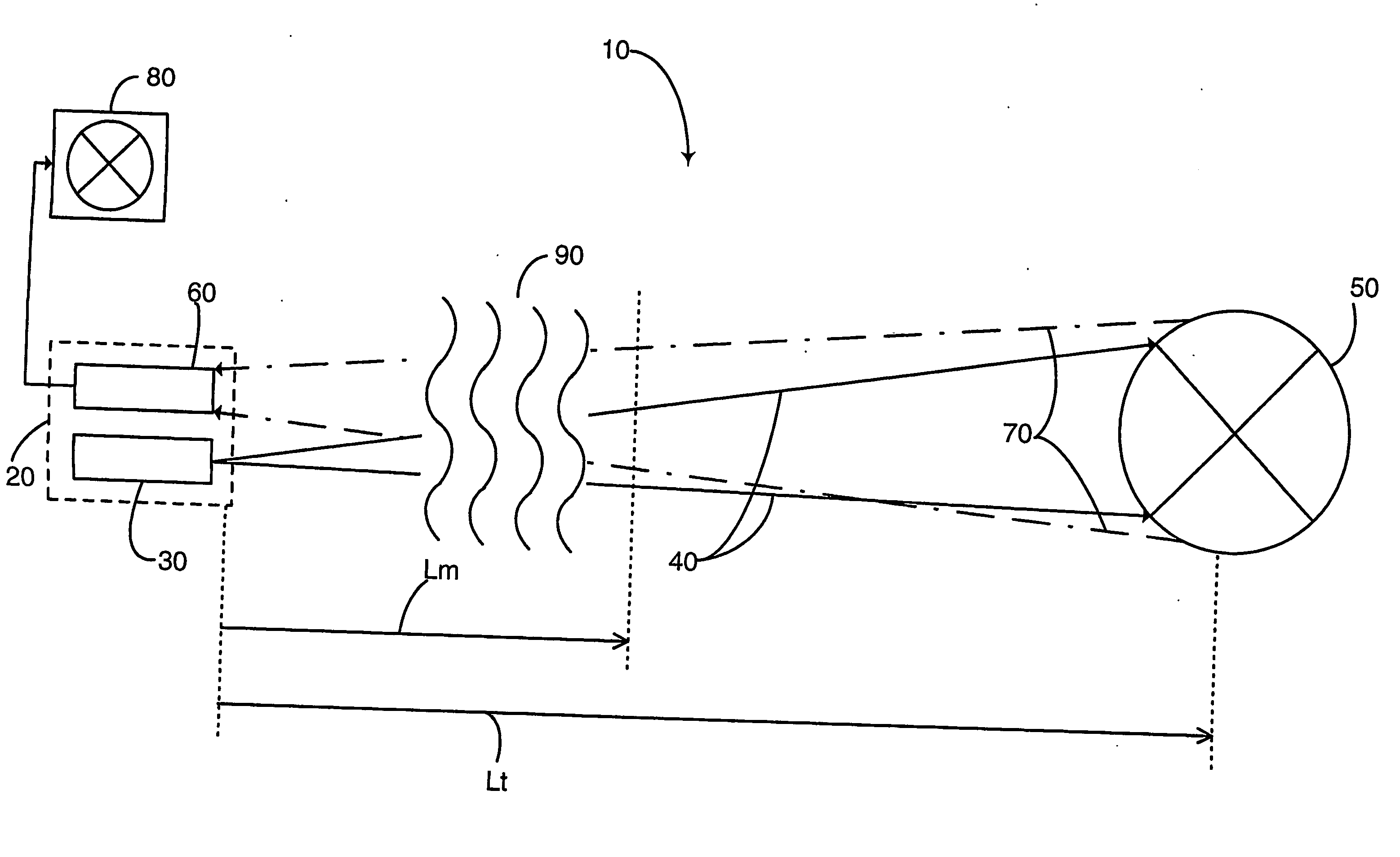
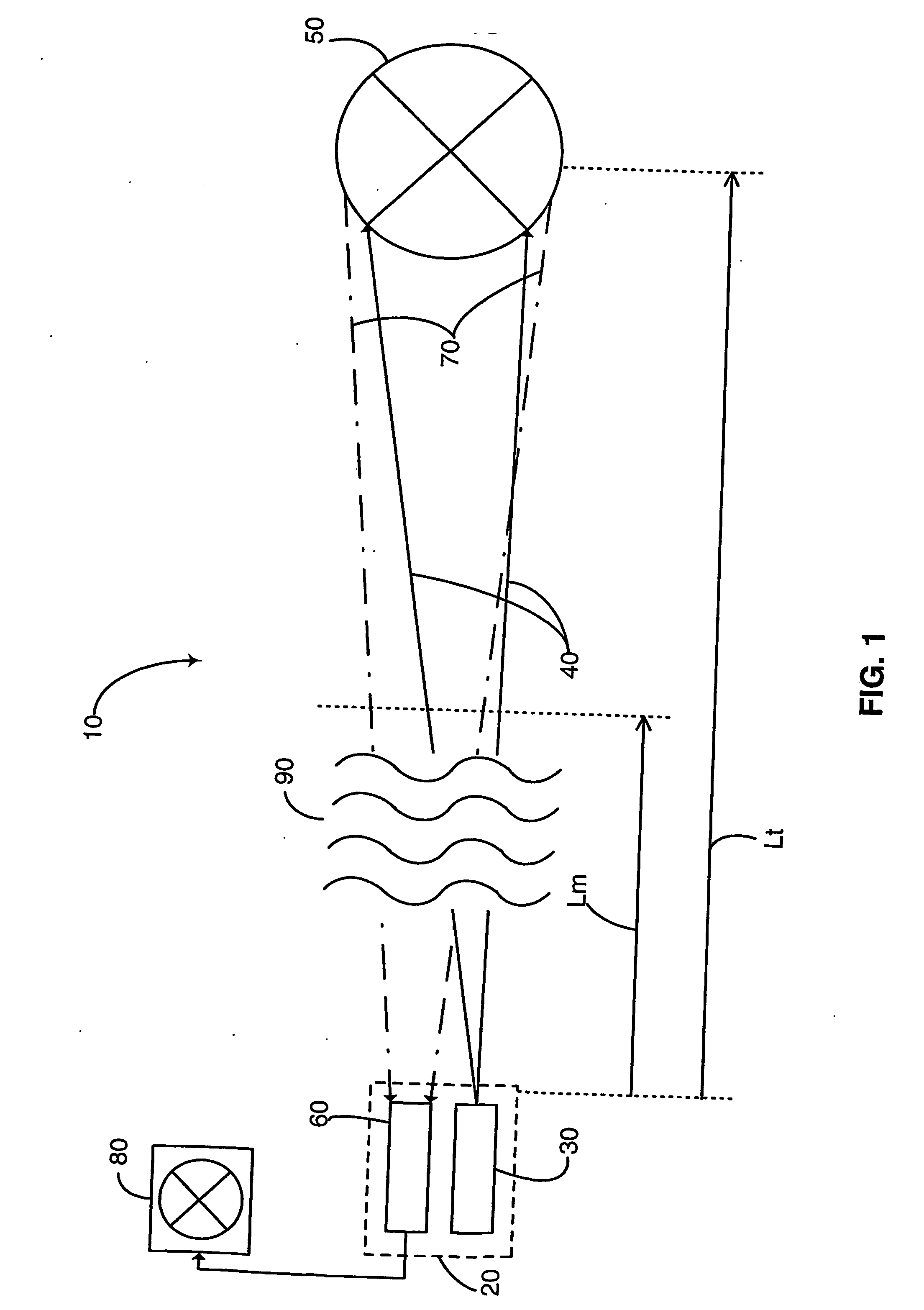
[0068] Optical assembly 460 includes array of objective lenses 461 that collimates laser beam 480 once more on its exit from embodiment 410, and receives returned reflexes 470 from the target that was illuminated by laser beam 480. Optical assembly 460 routes returned reflexes 470 via coupling lens assembly 462 unto camera assembly 490.

[0069] TV camera assembly 490 that processes and converts the reflexes from the illuminated target as received by optical assembly 460 into an image displayable on a TV, may include a CCD (charge coupled device) type sensor. The CCD sensor is coupled by relay lenses to a gated image intensifier, as known in the art. Alternatively, camera assembly 490 might also include a Gated Intensified Charge Injection Device (GICID), a Gated Intensified CCD (GICCD), a Gated Image Intensifier, a Gated Intensified Active Pixel Sensor (GIAPS), or any similar device.

[0070] It is noted that implementing any of the above mentioned sensor types enables advanced processi...

embodiment 510

[0074] In embodiment 510, laser beam 531 generated by laser device 530 is also of the DLA type. The beam of pulses is propagated from laser device 530 through optical fiber 532 to narrow collimator 522, which is installed on top of observation module 525, which is supported by support unit 560. Optical assembly 550, TV camera sensor 570, and the optical fiber exit of optical fiber 532 are also packaged in observation module 525. Support unit 560 provides for height and rotational adjustments. Support unit 560 can include a tripod, support legs 561 for fine adjustments, and an integral stabilization system (not shown), including, for example, viscous shock absorbers.

[0075] In embodiment 510, filter 571 (or an array of filters), as well as optical multiplier 572 (which may comprise many components), are installed in series in front of camera sensor 570. Prior to its entry into camera sensor 570, the reflex passes though filter 571 and optical multiplier 572 which is used to enlarge th...


PUM


Abstract

A gated camera imaging system and method, utilizing a laser device for generating a beam of long duration laser pulses toward a target. A camera receives the energy of light reflexes of the pulses reflected from the target. The camera gating is synchronized to be set OFF for at least the duration of time it takes the laser device to produce a laser pulse in its substantial entirety, including an end of the laser pulse, in addition to the time it takes the laser pulse to complete traversing a zone proximate to the system and back to the camera, and set ON for an ON time duration thereafter until the laser pulse reflects back from the target and is received in the camera. The laser pulse width substantially corresponds to at least the ON time duration. Preferably, the laser device includes a Diode Laser Array (DLA).

Description

FIELD OF THE INVENTION [0001] The present invention relates in general to the field of optical observation systems, and more particularly, to a long range, day and night TV channel observation system that operates using the gated imaging principle, and to methods implemented in such systems. BACKGROUND OF THE INVENTION [0002] Known within long-range surveillance and observation systems is the method of target detection and identification using TV systems that include a camera and a long focal lens. [0003] The light collecting capability of long focal lenses is limited due to volume, weight and cost constraints. [0004] Even when a camera includes in its setup an SLS (Star Light System), under conditions of inferior visibility, the natural background light intensity is not sufficient to enable the production of an image with adequate signal to noise ratio for exploiting the total resolution capability of the camera and to discern the fine details of the target in order to obtain its i...

Claims


Application Information

Patent Timeline
Patent Type & Authority Applications(United States)
IPC IPC(8): H04N7/00G01S7/486G01S17/18G01S17/86G01S17/89
CPCG01S7/486G01S17/89G01S17/107G01S17/023G01S17/18G01S17/86
Inventor INBAR, SHAMIRDAVID, OFER
Owner ELBIT SYST LTD
Why Eureka
Try Eureka