Roller chain sprocket with resilient cushion rings and root relief

a resilient cushion and roller chain technology, applied in the direction of gearing, bandages, hoisting equipment, etc., can solve the problems of increasing mismatch between components, increasing noise of roller chain drive, and several undesirable components so as to reduce the noise level of chain drive system, reduce the impact noise, and increase the fatigue life of elastomeric materials

Inactive Publication Date: 2006-11-09
HH CLOYES INC
View PDF25 Cites 28 Cited by
  • Summary
  • Abstract
  • Description
  • Claims
  • Application Information

AI Technical Summary

Benefits of technology

[0036] One advantage of the present invention is the provision of a sprocket that includes at least one cushion ring designed to increase the fatigue life of the elastomeric material that forms the cushion ring.
[0037] Another advantage of the present invention is the provision of a sprocket having two sets of sprocket teeth incorporating different tooth profiles, and at least one cushion ring that cooperates with the tooth profiles to reduce chain drive system noise levels below a noise level that either the tooth profiles or the cushion ring alone would produce.
[0038] Another advantage of the present invention is the provision of a sprocket having two different sets of asymmetrical sprocket teeth each incorporating root relief.
[0039] Another advantage of the present invention is the provision of a sprocket that phases or modulates the frequency of initial roller-to-engaging flank contacts of a first tooth profile relative to initial roller-to-engaging flank contacts of a second tooth profile thereby altering the rhythm of the initial roller-to-first engaging flank and the roller-to-second engaging flank contacts.
[0040] Yet another advantage of the present invention is the provision of a sprocket that minimizes impact noise generated by a roller-sprocket collision during meshing and / or broadband mechanical noise generated by unloaded rollers in a sprocket wrap.
[0041] A still further advantage of the present invention is the provision of a sprocket that provides a “staged” roller impact (i.e., an extension of the roller meshing interval) where a tangential roller-sprocket impact occurs first followed by a radial roller-sprocket impact at full mesh.

Problems solved by technology

Chain drive systems have several components of undesirable noise.
A major source of roller chain drive noise is the sound generated as a roller leaves the span and collides with the sprocket during meshing.
Under actual conditions as a result of feature dimensional tolerances, there will normally be a pitch mismatch between the chain and sprocket, with increased mismatch as the components wear in use.
Another source of chain drive noise is the broadband mechanical noise generated in part by shaft torsional vibrations and slight dimensional inaccuracies between the chain and the sprockets.
In particular, ordinary chain drive system wear comprises sprocket tooth face wear and chain wear.
However, adding pitch line clearance between sprocket teeth does not reduce chain drive noise caused by the roller-sprocket collision at impact.
An additional disadvantage of the sprocket disclosed in the '278 patent is that the rollers contact both engaging and disengaging flanks at full mesh.
A typical problem with cushion rings is one of durability.
That is, wear and compression set of the elastomeric material of the cushion rings can be expected in the area of maximum ring compression after repeated link impacts.
In addition, the cushion ring may eventually fatigue as a result of the repeated compression cycles during the meshing process.

Method used


Image

  • Roller chain sprocket with resilient cushion rings and root relief
  • Roller chain sprocket with resilient cushion rings and root relief
  • Roller chain sprocket with resilient cushion rings and root relief

Examples


Embodiment Construction

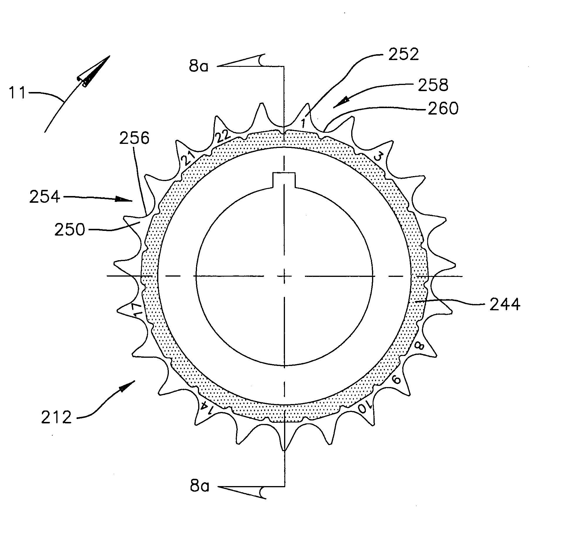
[0072] This invention relates to sprockets having symmetric and / or asymmetric teeth or tooth spaces, and also relates to sprockets having multiple arbitrarily positioned asymmetric tooth profiles (referred to herein as random engagement sprockets). In accordance with the present invention, any of these sprockets includes one or more cushion rings formed in accordance with the present invention. Furthermore, the particular sprockets and tooth profiles described herein are intended to be examples of preferred embodiments, and it is not intended that the invention be limited to these preferred embodiments in any way.

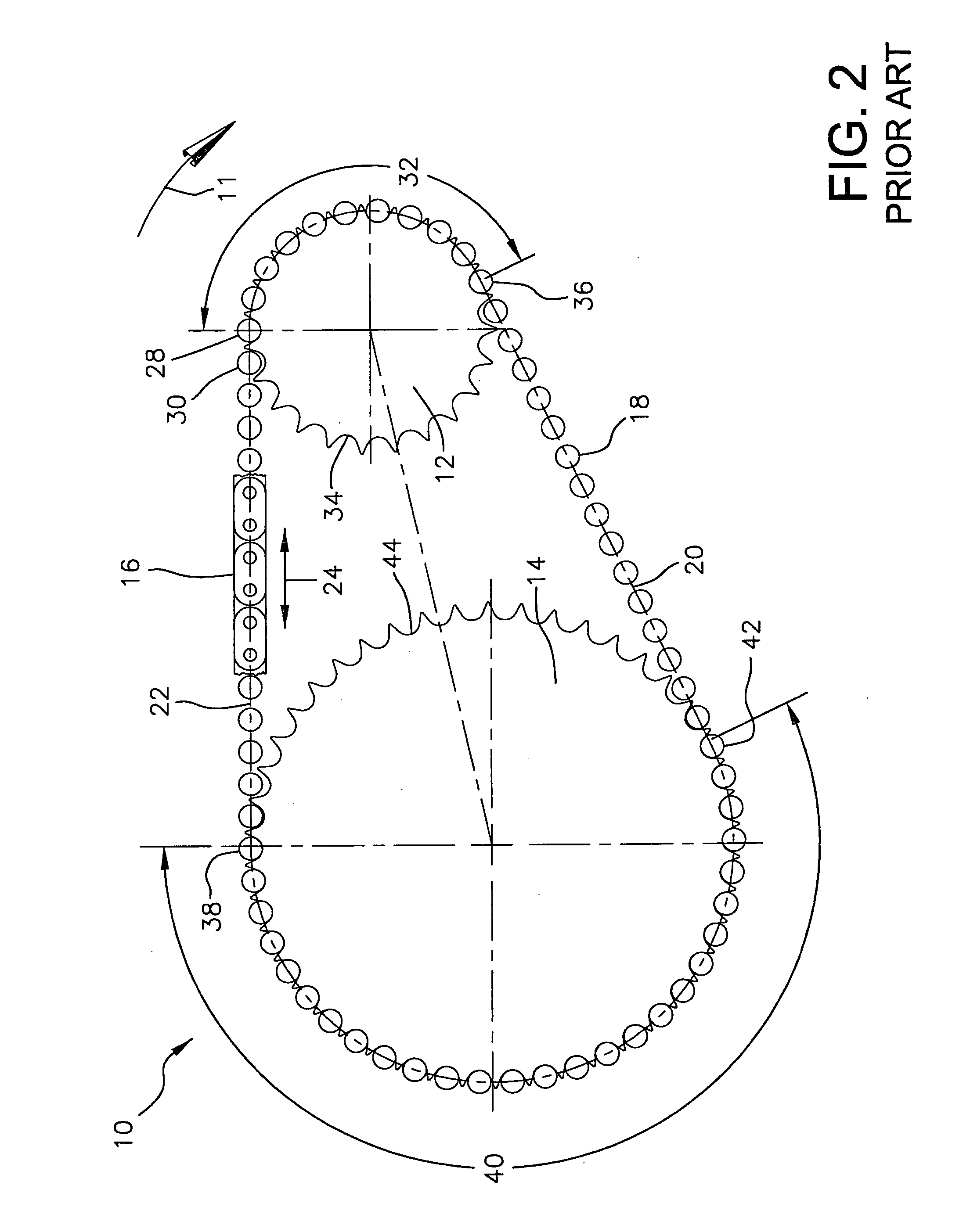
[0073] With reference now to FIG. 7, a roller chain drive system 210 that incorporates the features of the present invention therein. The roller chain drive system 210 includes a random-engagement drive sprocket 212, a driven sprocket 214, and a roller chain 216 having a number of rollers 218 which engage and wrap about sprockets 212, 214. The sprockets 212,214 rotate in a...


PUM

PropertyMeasurementUnit
pressure angleaaaaaaaaaa
flank pressure angleaaaaaaaaaa

Abstract

A sprocket includes a hub and a plurality of teeth projecting radially outwardly from the hub. At least one cushion ring is located adjacent the teeth, and the cushion ring defines a plurality of compression pads separated from each other by transverse grooves. Each of the compression pads is defined symmetrically about a circumferential mid-point. When part of a sprocket with symmetric tooth spaces, the cushion ring is being operable identically in first and second opposite rotational directions. In one arrangement, the compression pads each include a planar outer surface having a leading and a trailing end, wherein the leading end and trailing end are located a common radial distance from a center of the hub about which the sprocket rotates. The tooth spaces of the sprocket can be symmetric, asymmetric and the root surface can be relieved. The sprocket can include multiple tooth profiles distributed randomly about the hub.

Description

CROSS REFERENCE TO RELATED APPLICATIONS [0001] This application claims priority from U.S. application Ser. No. 09 / 728,698 filed Dec. 1, 2000, now U.S. Pat. No. 6,371,875, which claims priority from U.S. application Ser. No. 09 / 383,128 filed Aug. 25, 1999, now U.S. Pat. No. 6,179,741, which claims priority from U.S. provisional application Ser. No. 60 / 097,931 filed Aug. 25, 1998.BACKGROUND OF THE INVENTION [0002] The present invention relates to the automotive timing chain art. It finds particular application in conjunction with a roller chain sprocket for use in automotive camshaft drive applications and will be described with particular reference thereto. However, the present invention may also find application in conjunction with other types of chain drive systems and applications where reducing the noise levels associated with chain drives is desired. [0003] Roller chain sprockets for use in camshaft drives of automotive engines are typically manufactured according to one or more...

Claims


Application Information

Patent Timeline
Patent Type & Authority Applications(United States)
IPC IPC(8): F16H55/06F16H55/30F16H7/06F16H57/00
CPCF16H7/06F16H2055/306F16H57/0006F16H55/30F16H2055/086
Inventor YOUNG, JAMES D.
Owner HH CLOYES INC
Why Eureka
Try Eureka