Heat exchanger having powder coated elements

a technology of heat exchanger and element, which is applied in the field of heat exchangers, can solve the problems of insufficient corrosion protection, metal corrosion, weakening of elements, etc., and achieve the effect of facilitating heat exchange with air

Inactive Publication Date: 2006-11-16
PARAGON TECH
View PDF46 Cites 12 Cited by
  • Summary
  • Abstract
  • Description
  • Claims
  • Application Information

AI Technical Summary

Benefits of technology

[0012] In still another aspect, the heat exchanger is adapted to be used in a high sulfur content air and high temperature environment. Also, the heat exchanger is adapted to be used to reduce the temperature of a flue gas being emitted from a fossil burning power generator prior to the gas being ejected into the environment.
[0015] The aforementioned needs may also be satisfied by a heat exchange assembly for a heat exchanger having a heat exchanging body that rotates in a first direction with respect to a housing. In one embodiment, the assembly comprises a plurality of heat exchange members that are formed so as define a heat exchange surface, wherein the heat exchange members are positioned in the heat exchanging body to thereby facilitate heat exchange with air. In addition, the assembly further comprises a protective layer disposed on the heat exchange surface, wherein the protective layer comprises a powder coating that inhibits corrosion of the heat exchange members.

Problems solved by technology

In operation, the heat exchangers are usually exposed to harsh environments that tend to induce corrosion of the metal of the heat exchanger, including the seals and the heat exchange elements.
The corrosive environment leads to pitting in the degeneration of the metal in the heat exchange elements, structurally weakening the elements.
Often, the enamel coating contains bubbles such that full corrosion protection is not afforded.
In addition, the enamel coating is susceptible to cracking when subjected to mechanical stresses.
Such breach of the coating allows corrosion inducing agents to come in contact with the metal, thereby causing corrosion, which in turn reduces the effectiveness of the heat exchanger.

Method used


Image

  • Heat exchanger having powder coated elements
  • Heat exchanger having powder coated elements
  • Heat exchanger having powder coated elements

Examples


Embodiment Construction

[0035] In the following detailed description, terms of orientation such as “top,”“bottom,”“upper,”“lower,”“front,”“rear,” and “end” are used herein to simplify the description of the context of the illustrated embodiments. Likewise, terms of sequence, such as “first” and “second,” are used to simplify the description of the illustrated embodiments. Because other orientations and sequences are possible, however, the present invention should not be limited to the illustrated orientation. Those skilled in the art will appreciate that other orientations of the various components described below are possible.

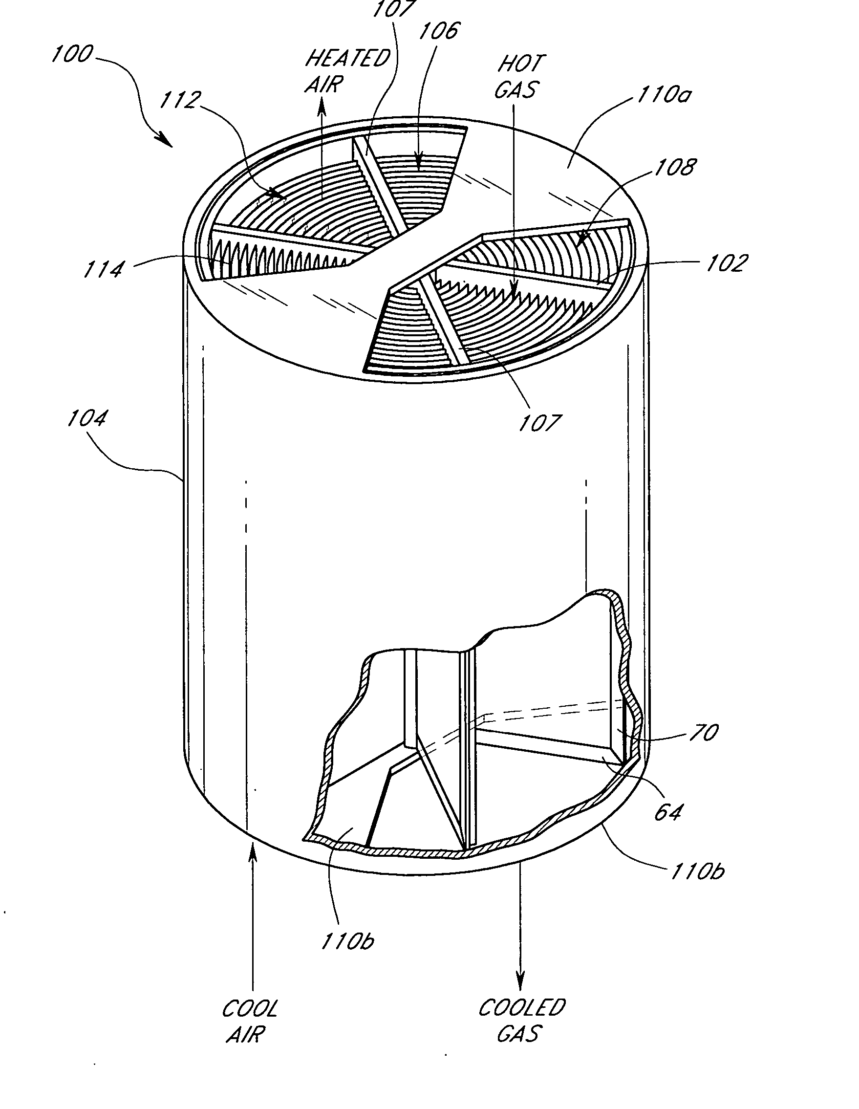
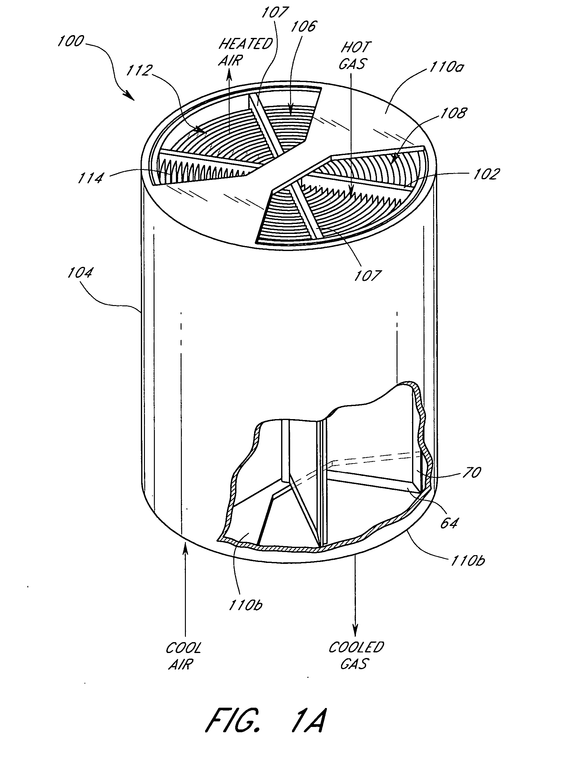
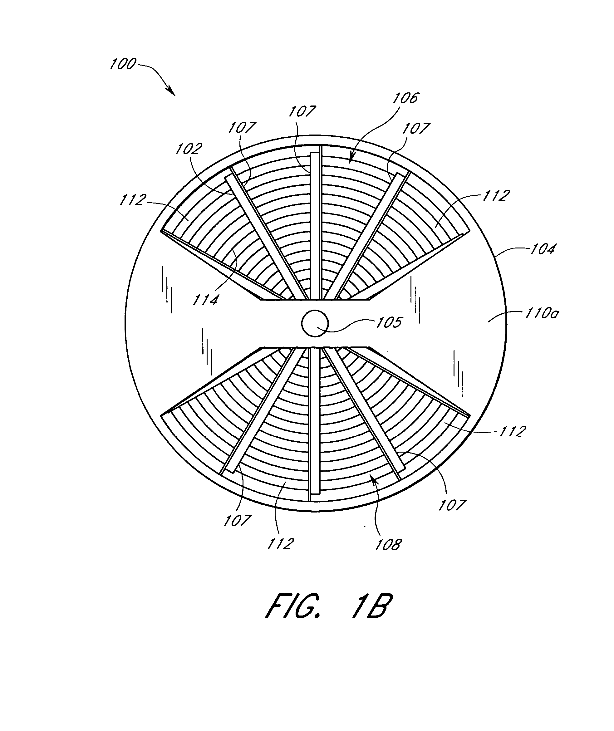
[0036] Reference will now be made to the drawings wherein like numerals refer to like parts throughout. FIGS. 1A-7 illustrate various aspects related to a heat exchanger having powder coated elements that inhibit corrosion. Various other aspects of the present teachings will be described in greater detail herein below with reference to the drawings. In general, it should be apprecia...


PUM

PropertyMeasurementUnit
thicknessaaaaaaaaaa
thicknessaaaaaaaaaa
temperatureaaaaaaaaaa

Abstract

Powder coated heat exchange elements for a heat exchanger. Powder coating provides improved protective coating on surfaces of heat exchange elements. In many applications, the heat exchange elements are subjected to harsh operating conditions that promote corrosion. Traditional enamel coating tends to fracture when subjected to mechanical stresses thereby allowing corrosion inducing agents to penetrate and corrode the underlying surfaces. Powder coating reduces breaches in the protective layer. Powder coating may be adapted to withstand high temperatures so as to make them suitable for use in harsh operating environments. One such environment can be found in the processing of flue gas from fossil burning power generators, where the flue gas has a relatively high temperature and high sulfur content.

Description

RELATED APPLICATIONS [0001] This application is a continuation-in-part application of U.S. application Ser. No. 10 / 793,182, filed Mar. 3, 20004, which claims the benefit of U.S. Provisional Application No. 60 / 452,065 entitled “Rotary Heat Exchanger with Powder Coated Heat Exchange Elements” filed Mar. 3, 2003, both of which are hereby incorporated by reference and should be considered a part of this specification.Background [0002] 1. Field [0003] The present teachings relate to heat exchangers and, in particular, relates to a heat exchanger having powder coated elements that inhibit corrosion. [0004] 2. Description of the Related Art [0005] Heat exchangers in various forms are included in systems that control the condition of air. Conventional heat exchangers include a heater that takes input air and outputs air with a higher temperature. A cooler, generally referred to as an air conditioner, takes input air and outputs air with a lower temperature. In both cases, the change in temp...

Claims


Application Information

Patent Timeline
Patent Type & Authority Applications(United States)
IPC IPC(8): F28F13/18
CPCF28D19/044F28D19/047Y10T29/4935F28G9/005F28F7/00F28F19/02
Inventor KASER, JACKKASER, DEBORAH
Owner PARAGON TECH
Why Eureka
Try Eureka