
Constant voltage power supply

a constant voltage and power supply technology, applied in the direction of electric variable regulation, process and machine control, instruments, etc., can solve the problems of complex circuits and extreme slow response speed, and achieve the effect of less current, excellent ripple rejection, and inferior ripple rejection

Inactive Publication Date: 2006-11-16
RICOH KK
View PDF7 Cites 11 Cited by
  • Summary
  • Abstract
  • Description
  • Claims
  • Application Information

AI Technical Summary

Benefits of technology

[0013] Accordingly, it is a general object of the present invention to provide a constant voltage power supply in which the above-described disadvantages are eliminated.
[0014] A more specific object of the present invention is to provide a constant voltage power supply that can be free of the complication of the conventional constant voltage power supply and can improve load transient response and supply voltage variation response in a standby mode without increasing current consumption.
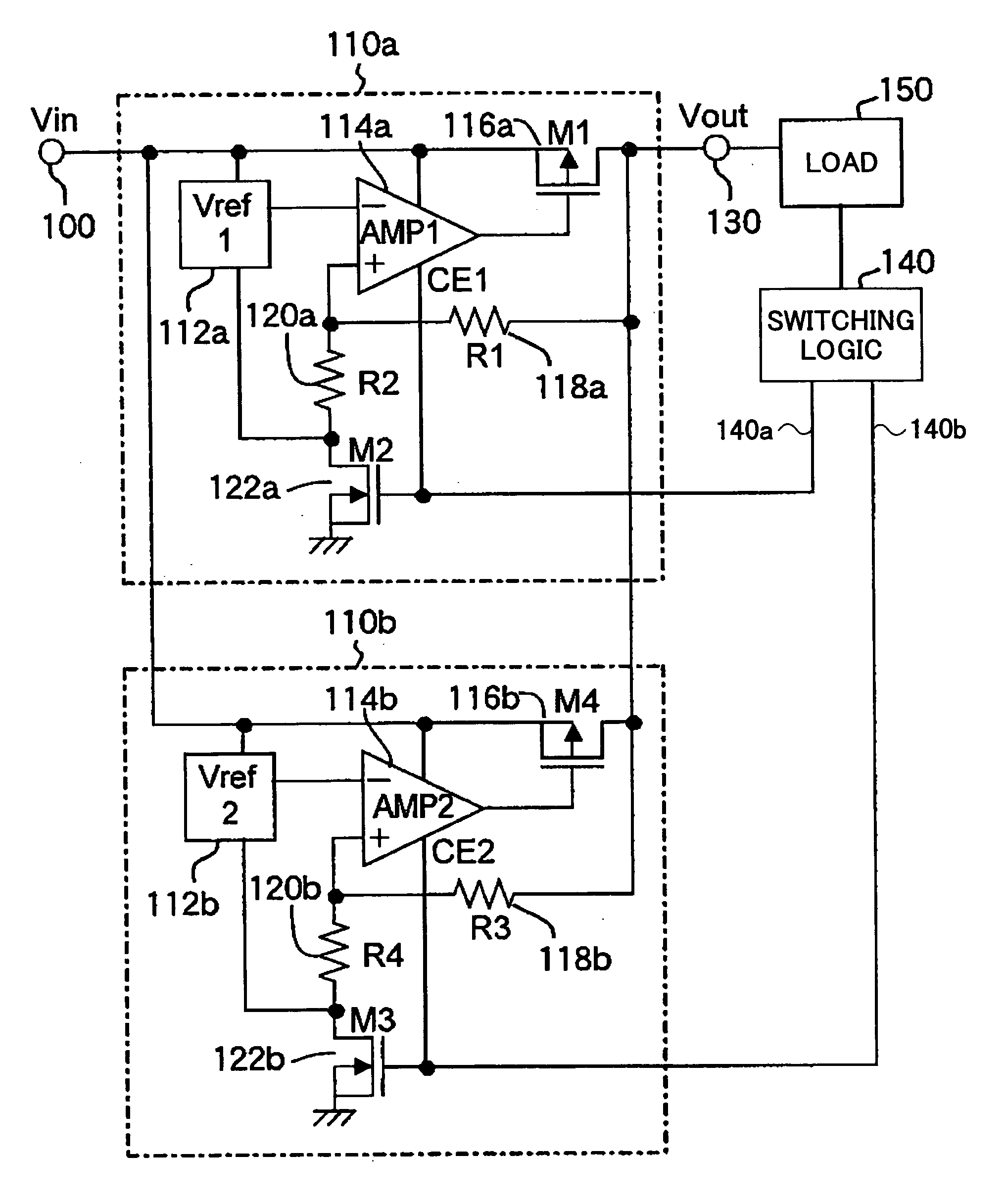
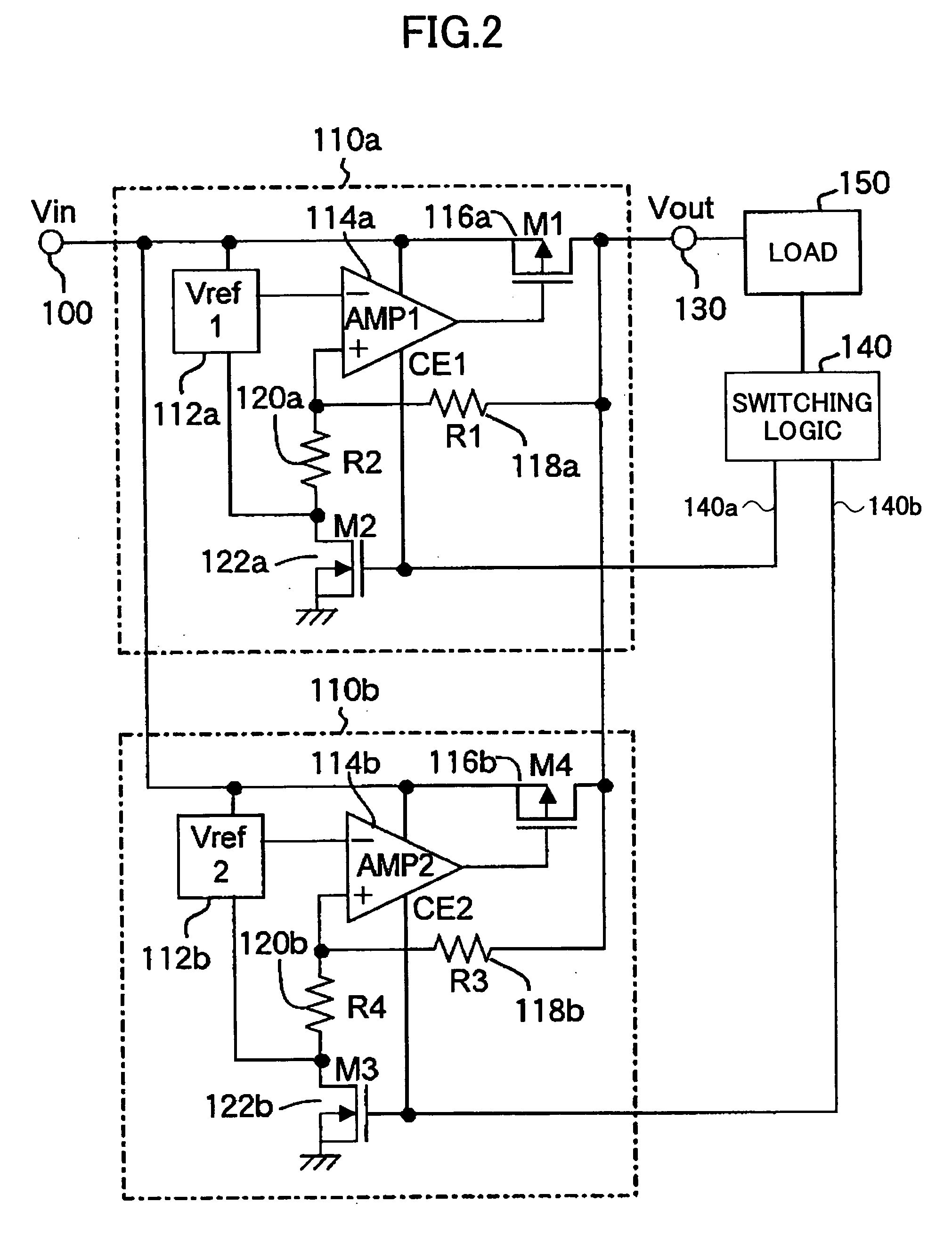
[0016] According to one aspect of the present invention, a first constant voltage circuit that consumes a large amount of current but has excellent ripple rejection and load transient response and a second constant voltage circuit that is inferior in ripple rejection and load transient response but consumes less current are connected in parallel. The first constant voltage circuit is caused to operate when a load is in an active state, and the second constant voltage circuit is caused to operate when the load is in a standby state. As a result, it is possible to improve current consumption by the power supply circuit when the load is in the standby state. Further, the output transistor of the second constant voltage circuit is reduced in size. Accordingly, there is no significant decrease in response, which can be much better than conventionally. Moreover, since the output transistor of the second constant voltage circuit is reduced in size, it is possible to prevent an increase in IC chip area.

Problems solved by technology

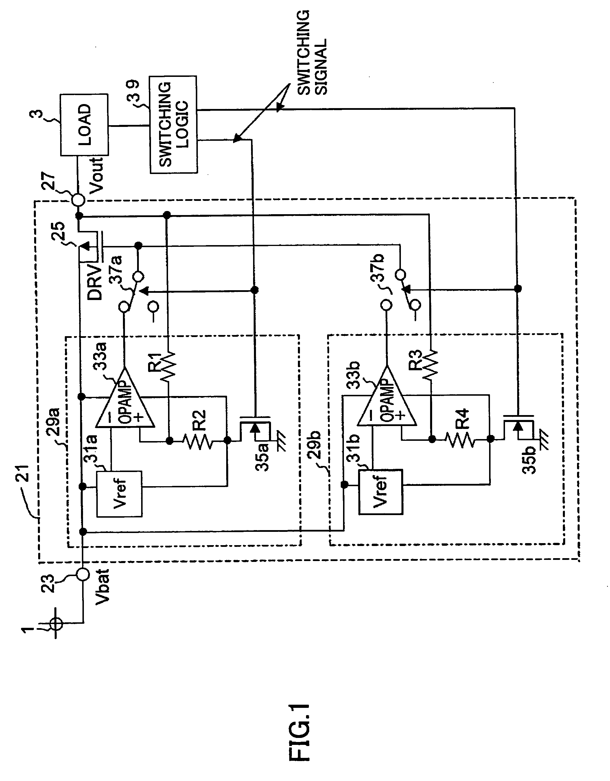
Controlling the output transistor 25, having such a large gate area as to be able to control large current, by such an operational amplifier results in extremely slow response speed.
Further, the two changeover switches (the switch parts 37a and 37b) are required to switch an output to be connected to the gate of the output transistor 25 between the outputs of the two operational amplifiers 33a and 33b, thus resulting in a complicated circuit.

Method used


Image

  • Constant voltage power supply
  • Constant voltage power supply
  • Constant voltage power supply

Examples


Embodiment Construction

[0021] A description is given below, with reference to the accompanying drawings, of an embodiment of the present invention.

[0022]FIG. 2 is a circuit diagram illustrating a constant voltage power supply according to the embodiment of the present invention. The constant voltage power supply includes a first (high-speed) constant voltage circuit 110a and a second (low-speed) constant voltage circuit 110b, each of which converts an input voltage (Vin) into a predetermined voltage and outputs the predetermined voltage. The inputs of the first and second constant voltage circuits 110a and 110b are connected in parallel to an input terminal (Vin) 100, and the outputs of the first and second voltage circuits 110a and 110b are connected in parallel to an output terminal (Vout) 130. A power supply such as a battery (not graphically illustrated) is connected to the input terminal 100 of the constant voltage power supply. Further, a load 150 that is an apparatus such as a cellular phone is co...


PUM


Abstract

A constant voltage power supply for supplying power to a load that switches between an active state and a standby state is disclosed. The constant voltage power supply includes first and second constant voltage circuits different in transient response and current consumption. The input of each of the first and second constant voltage circuits is connected to the input terminal of the constant voltage power supply, and the output of each of the first and second constant voltage circuits is connected to the output terminal of the constant voltage power supply. A switching signal generation circuit outputs a switching signal so as to cause the first operational amplifier to operate when the load is in the active state, and to cause the second operational amplifier to operate when the load is in the standby state.

Description

TECHNICAL FIELD [0001] The present invention relates generally to constant voltage power supplies, and more particularly to a constant voltage power supply supplying power to a load that switches between an active state and a standby state. BACKGROUND ART [0002] A constant voltage power supply that has a constant voltage circuit to supply stable voltage is employed as a power supply for, for instance, cellular phones. The constant voltage power supply has a constant voltage circuit that consumes a large amount of current (a high-speed constant voltage circuit) in order to improve power supply rejection ratio (PSRR), or ripple rejection, and load transient response. Accordingly, when the constant voltage power supply is applied to an apparatus whose load has an active mode (active state) and a sleep mode (standby state), such as a cellular phone, the amount of unnecessarily consumed current is increased in the sleep mode, which does not require high PSRR and load transient response. ...

Claims


Application Information

Patent Timeline
IPC IPC(8): G05F1/00G05F1/56G05F1/565G11C5/14
CPCG11C5/143G05F1/565G05F1/56
Inventor ITOH, KOHZOH
Owner RICOH KK
Learn More