Structure Of Embedded Capacitors And Fabrication Method Thereof

a technology of embedded capacitors and fabrication methods, which is applied in the field of printed circuit boards, can solve the problems that traditional methods for forming the conductive terminals of embedded capacitors such as lamination of copper foils or using resin coated copper foils prepared in advance are not suitable for the new structure, and achieve the effects of reducing manufacturing costs, increasing yield rates, and different capacitances

Inactive Publication Date: 2006-11-16
YANG WEI CHUN +1
View PDF4 Cites 0 Cited by
  • Summary
  • Abstract
  • Description
  • Claims
  • Application Information

AI Technical Summary

Benefits of technology

[0014] The present invention has the following advantages. First, the present invention has a better flexibility for routing and design than that of the common planar capacitor structure. The present invention also provides better signal integrity when used in high frequency and high speed electric circuits.
[0016] Thirdly, as materials having different dielectric constants are used in the same layer of the new structure to achieve significantly different capacitances, the present invention requires less number of layers and thereby reduces manufacturing cost and increases the yield rate.

Problems solved by technology

Traditional methods for forming the conductive terminals of the embedded capacitors such as the lamination of copper foils or using resin coated copper foils prepared in advance are not suitable for the new structure.

Method used


Image

  • Structure Of Embedded Capacitors And Fabrication Method Thereof
  • Structure Of Embedded Capacitors And Fabrication Method Thereof
  • Structure Of Embedded Capacitors And Fabrication Method Thereof

Examples


Embodiment Construction

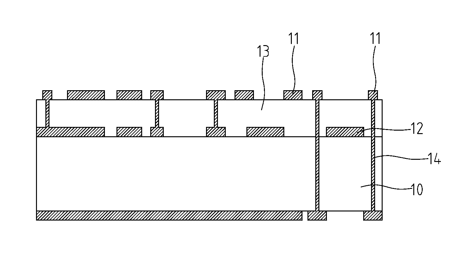
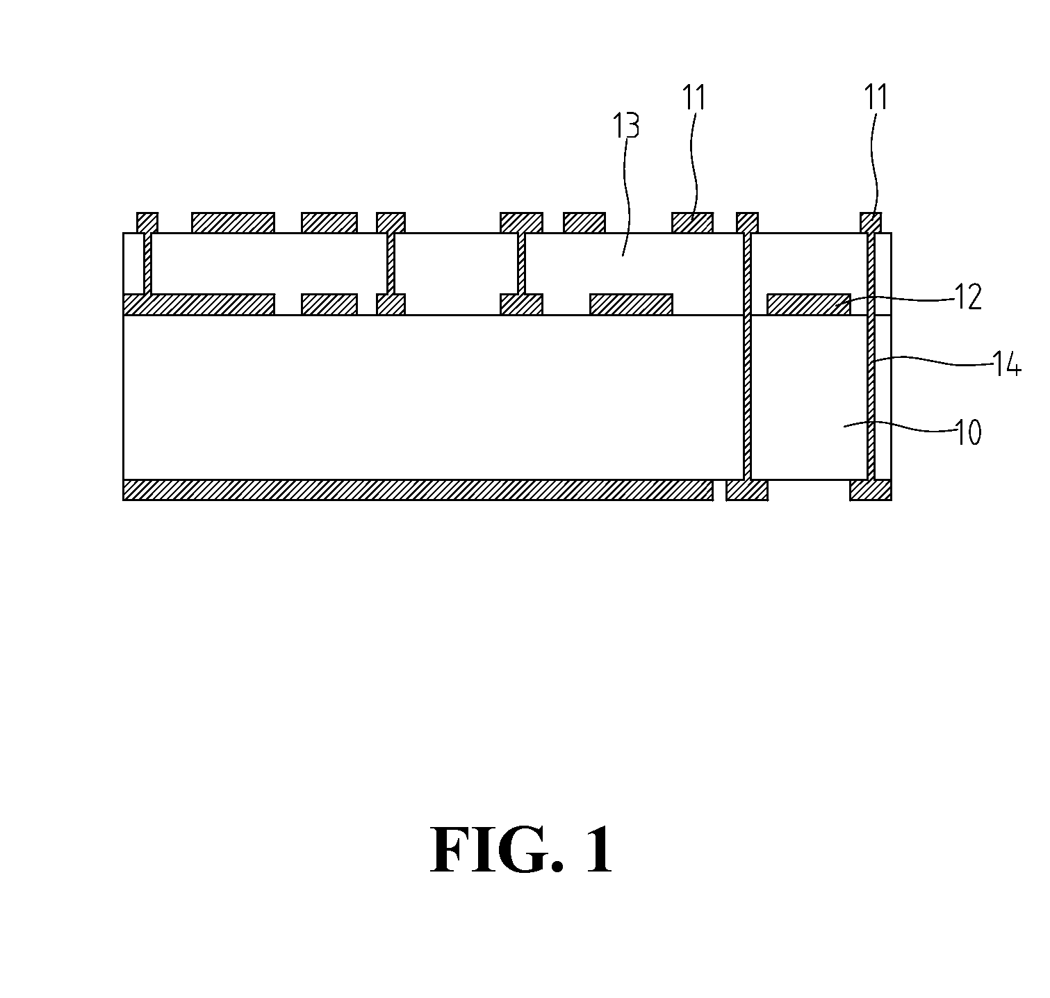
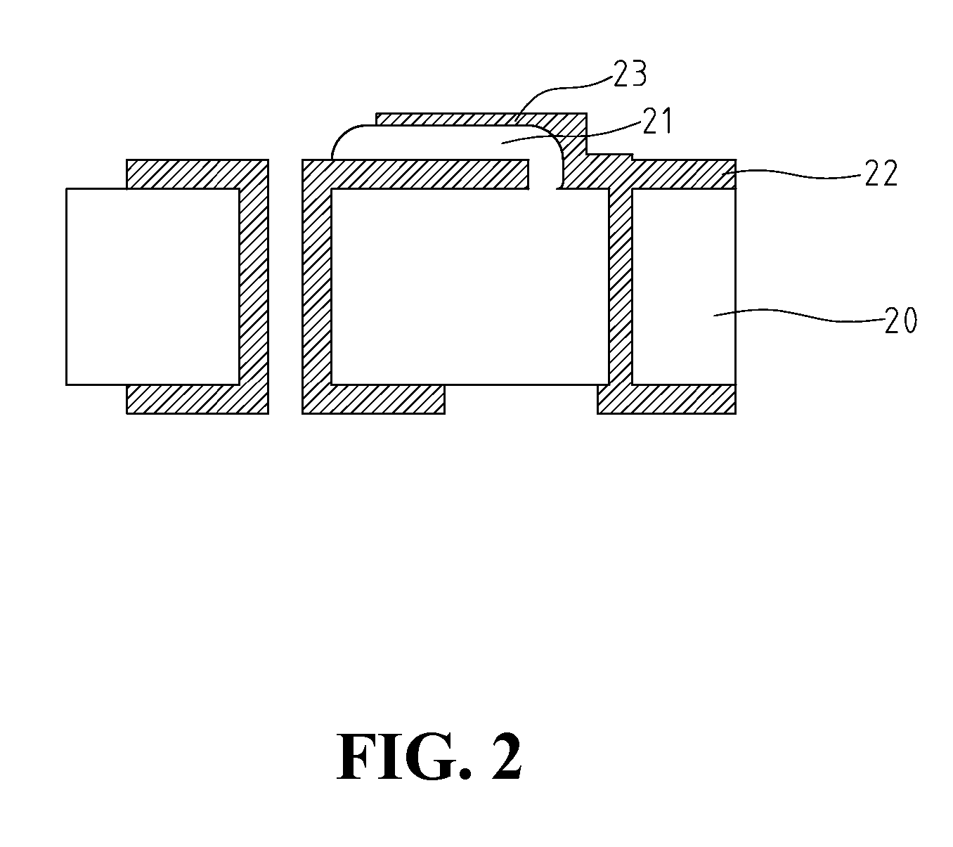
[0020]FIG. 2 is a sectional view of the singulated coplanar capacitor structure according the present invention. As shown in FIG. 2, a dielectric layer made of an inorganic material having a specific dielectric constant is coated or laminated on the substrate 20. Then a subtractive method such as wet etching, laser trimming, or plasma etching is applied to the dielectric layer to form a pattern 21. The pattern 21 can also be formed directly on the substrate 20 using an additive method such as screen printing and thin film deposition. The inorganic material can be a polymer thick film material, a metallic oxide, or a ceramic capacitor material.

[0021] At places where the dielectric layer is etched away, a polymer having a different dielectric constant is coated on the substrate 20 to form a second pattern 22. The two patterns 21 and 22 jointly form a singulated coplanar structure. The polymer can be a polymer capacitive paste.

[0022] Then, on top of the two patterns, upper conductive...


PUM


Abstract

A new structure is provided to replace the existing common planar capacitor structure used in printed circuit boards. The common planar capacitor structure utilizes a single dielectric layer and embedded capacitors with different capacitances achieved by adjusting the sizes of the embedded capacitors' conductive terminals. Since general applications usually require capacitors whose capacitance range covers several orders of magnitude, these embedded capacitors have significant differences in terms of their conductive terminals' sizes. This will make the manufacturing process more complicated and difficult. The new structure combines inorganic material having a specific dielectric constant and polymer having another specific dielectric constant into a singulated coplanar capacitor structure.

Description

CROSS-REFERENCES TO RELATED APPLICATIONS [0001] This is a division of U.S. application Ser. No. 10 / 998,076, filed Nov. 26, 2004.BACKGROUND OF THE INVENTION [0002] 1. Field of the Invention [0003] The present invention relates to the printed circuit board, and in particular to the structure and fabrication method of embedded capacitors in the printed circuit board. [0004] 2. The Prior Arts [0005] The printed circuit board with embedded passive elements, due to its size reduction and better electrical characteristics, has become a mainstream technology for printed circuit boards. [0006] Currently, as shown in FIG. 1, the embedded capacitors of a printed circuit board are usually formed using a common planar capacitor structure. With this structure, the embedded capacitors are made of a dielectric layer 13 having a specific dielectric constant on a substrate 10. On the bottom and top of the dielectric layer 13, the conductive terminals 11 and 12 of the embedded capacitors are formed by...

Claims


Application Information

Patent Timeline
Patent Type & Authority Applications(United States)
IPC IPC(8): H01L21/8244
CPCH05K1/162H05K2201/09763H05K3/4602
Inventor YANG, WEI-CHUNCHANG, CHIEN-WEI
Owner YANG WEI CHUN
Why Eureka
Try Eureka