

System and methods for processing analyte sensor data for sensor calibration
- Summary
- Abstract
- Description
- Claims
- Application Information
AI Technical Summary
Benefits of technology
Problems solved by technology
Method used
Image

Examples
example i
[0493] As described above, benchtop testing of a sensor prior to insertion can be used to calibrate sensor data after the sensor is inserted. FIG. 27 shows in-vivo sensitivity (as calculated using retrospective calibration) vs. in-vitro sensitivity (collected prior to implant), of 16 short term sensors implanted in humans. Least-squares regression was used to define the predictive relationship between in-vitro and in-vivo sensitivities (e.g., min vivo=2.99*min vitro+26.62), as shown in FIG. 27. This relationship was applied to a sensor used in the above-described experiment. The comparison of blood glucose values with the in-vitro calibrated sensor is shown in FIGS. 28 and 29. Predicted in-vivo sensitivity was assumed for calibration throughout the first day. The mean absolute relative difference found across 43 matched pairs over 3 days was 20.17%. In-vivo sensitivity is usually greater than in-vitro sensitivity (typically 2-3× higher). This may be due to enhanced transport of gluc...
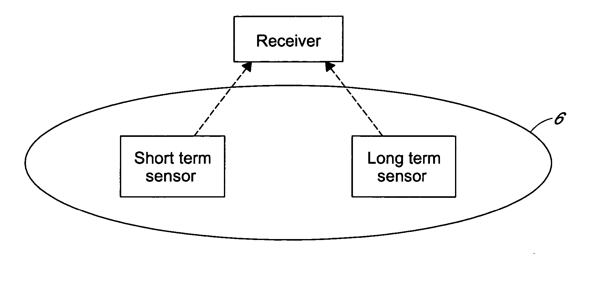
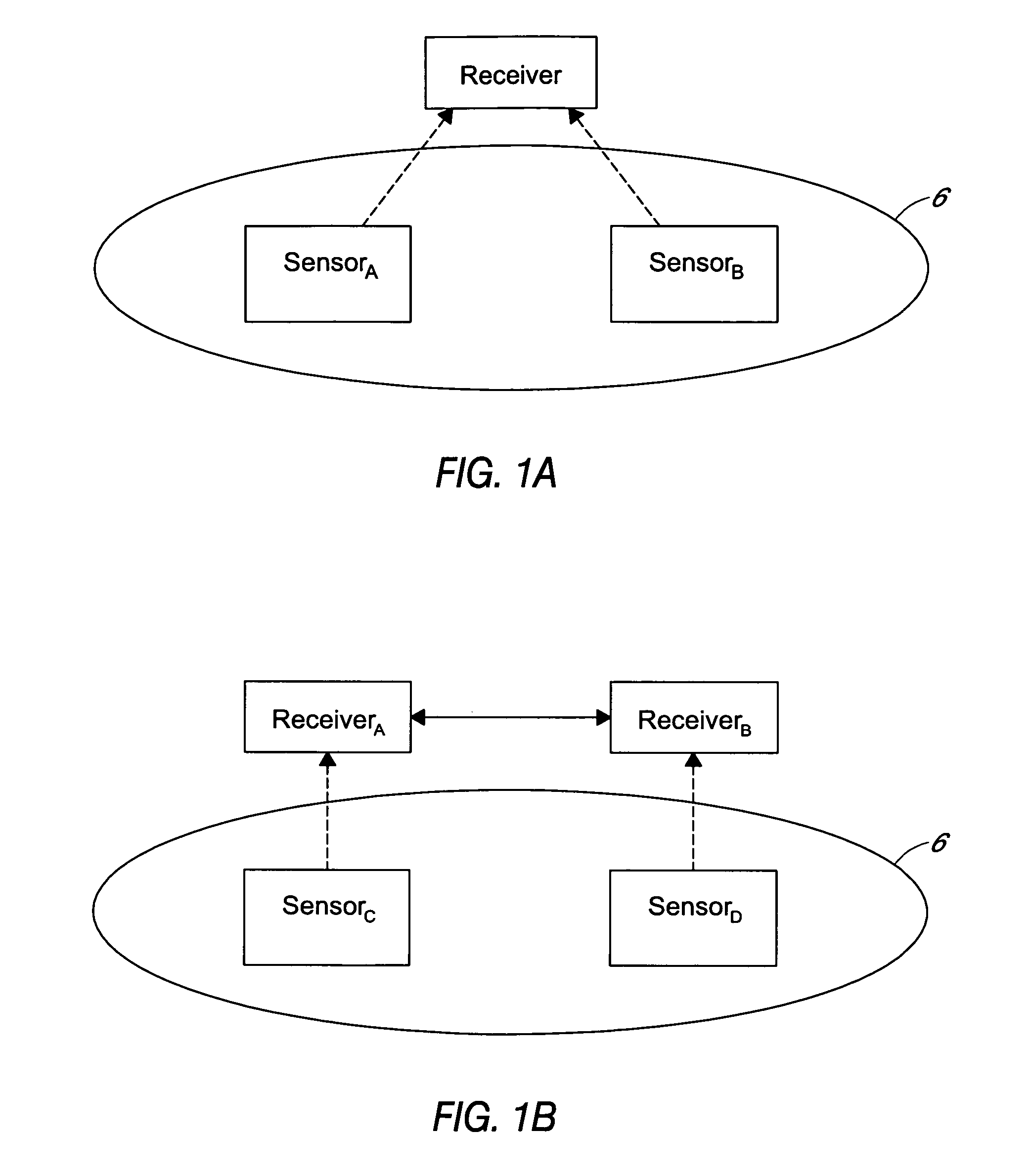
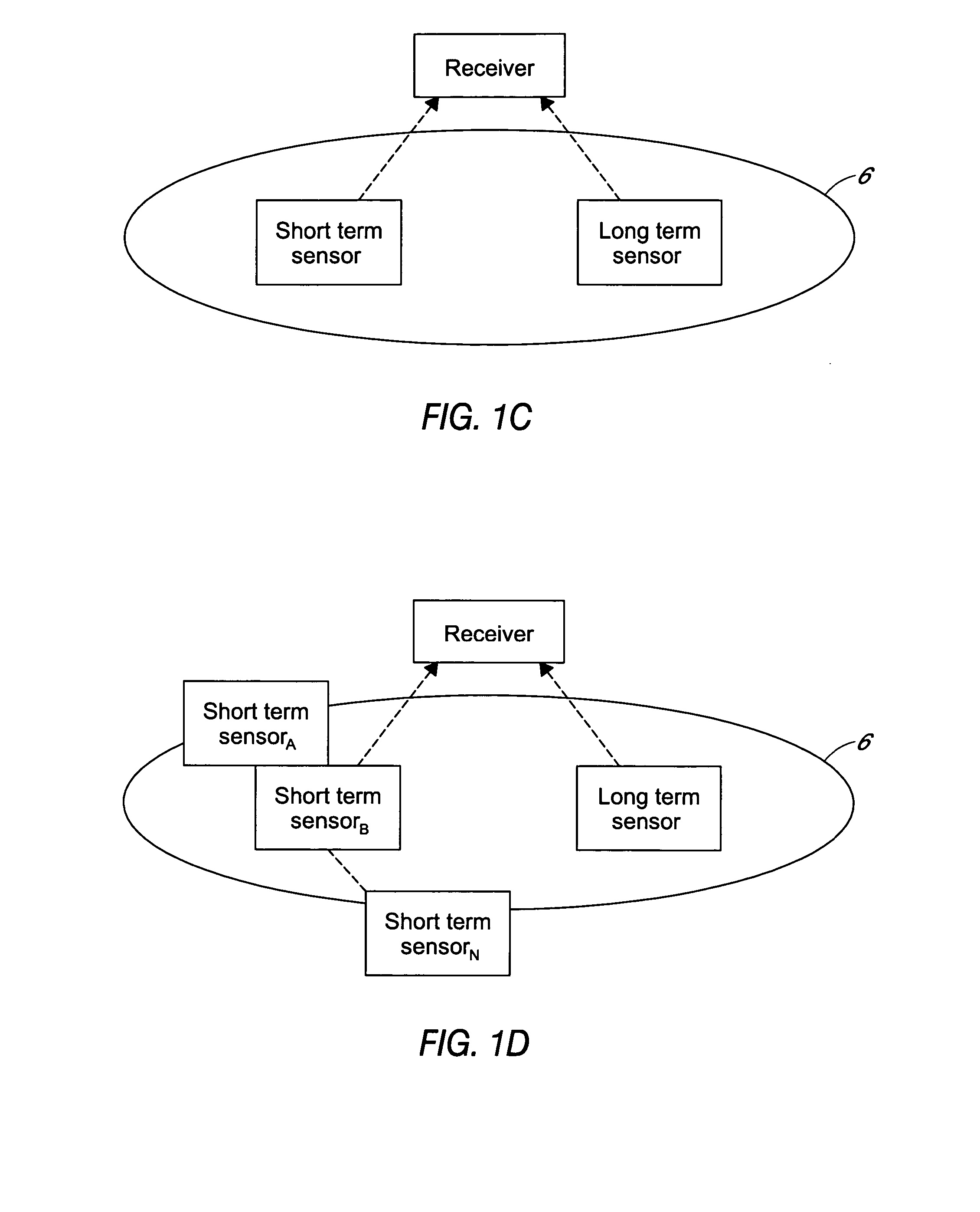
example ii
[0494] In this example, one substantially continuous glucose sensor was used to calibrate another substantially continuous glucose sensor, where both sensors were used in the same host. The data specifically illustrates the use of a short-term (e.g., transcutaneous) sensor to calibrate a long term (e.g., implantable) sensor, but the methods described are applicable to other combinations, including (1) use of a short-term sensor to calibrate another short term sensor; (2) use of a long-term sensor to calibrate another long-term sensor; (3) use of a long term sensor to calibrate a short term sensor.
[0495] As discussed herein, calibration of an enzyme-electrode based glucose sensor consists of solving the line
y=m×+b
for m and b, where y denotes the sensor signal (in units of A / D counts), x the estimated glucose concentration (mg / dl), m the sensor sensitivity to glucose (counts / mg / dl), and b the baseline signal unrelated to glucose (counts). If two glucose sensors are used concurrent...
example iii
[0500] Referring now to FIG. 32, in this example, sensor data from a short term analyte sensor was used to calibrate a subsequently employed short term sensor. Short term data was collected over a two and a half-day time period from a substantially continuous short term sensor employed on a human host. Finger stick glucose measurements (referred to in FIG. 32 as “Calpts” and depicted with large round dots) were used to calibrate Sensor No. 1. Glucose values (read off of the left y-axis) were derived from the Calibrated Sensor No. 1 sensor data. The Calibrated Sensor No. 1 data is referred to in FIG. 32 as “Calglucose 1” and depicted as small dots.
[0501] On Day 3, a second substantially continuous short term sensor (referred to in FIG. 32 as “Sensor2”) was employed on the same host as Sensor No. 1, and sensor data was collected about every 5 minutes for one day (e.g., 288 data points). Digital count data (read off of the right y-axis) from the Sensor No. 2 is depicted in FIG. 32 as ...
PUM
 Abstract
Description
Claims
Application Information