
Holder for a cutting tool for metalworking and a method for the production of a holder for a cutting tool

a technology for metalworking and cutting tools, applied in the field of holders for cutting tools and cutting tools, can solve the problems of increasing the fatigue strength of such holders and satisfying the fatigue strength of the holders, and achieve the effect of improving fatigue strength

Inactive Publication Date: 2006-11-23
SANDVIK INTELLECTUAL PROPERTY AB
View PDF10 Cites 13 Cited by
  • Summary
  • Abstract
  • Description
  • Claims
  • Application Information

AI Technical Summary

Benefits of technology

[0007] The primary object of the present invention is to provide a holder body having improved fatigue strength at high loads.
[0008] Another object of the present invention is to provide a holder body having low risk of crack formation.
[0009] Still another object of the present invention is to provide a holder body that is simple and inexpensive to manufacture.
[0010] An additional object of the present invention is to provide a holder body having a long service life at high loads.

Problems solved by technology

Thus, there is a growing need to increase the fatigue strength of such holder bodies, and particularly in and adjacent to the insert seats.
However, it has turned out that this method does not result in satisfying fatigue strength of the holder body at exceptionally high loads, such as greater than 60% of the yield point in tension of the material.

Method used


Image

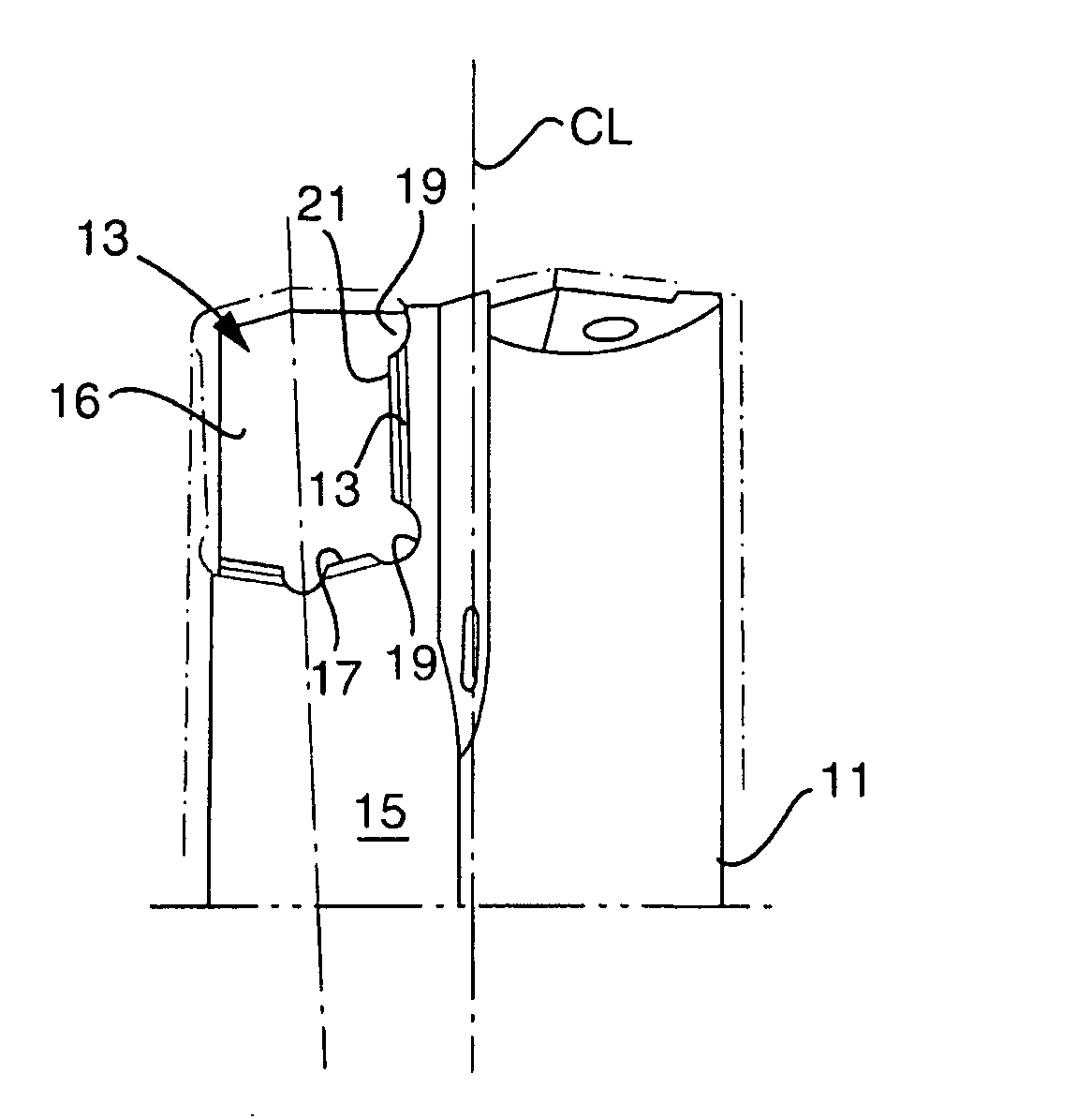
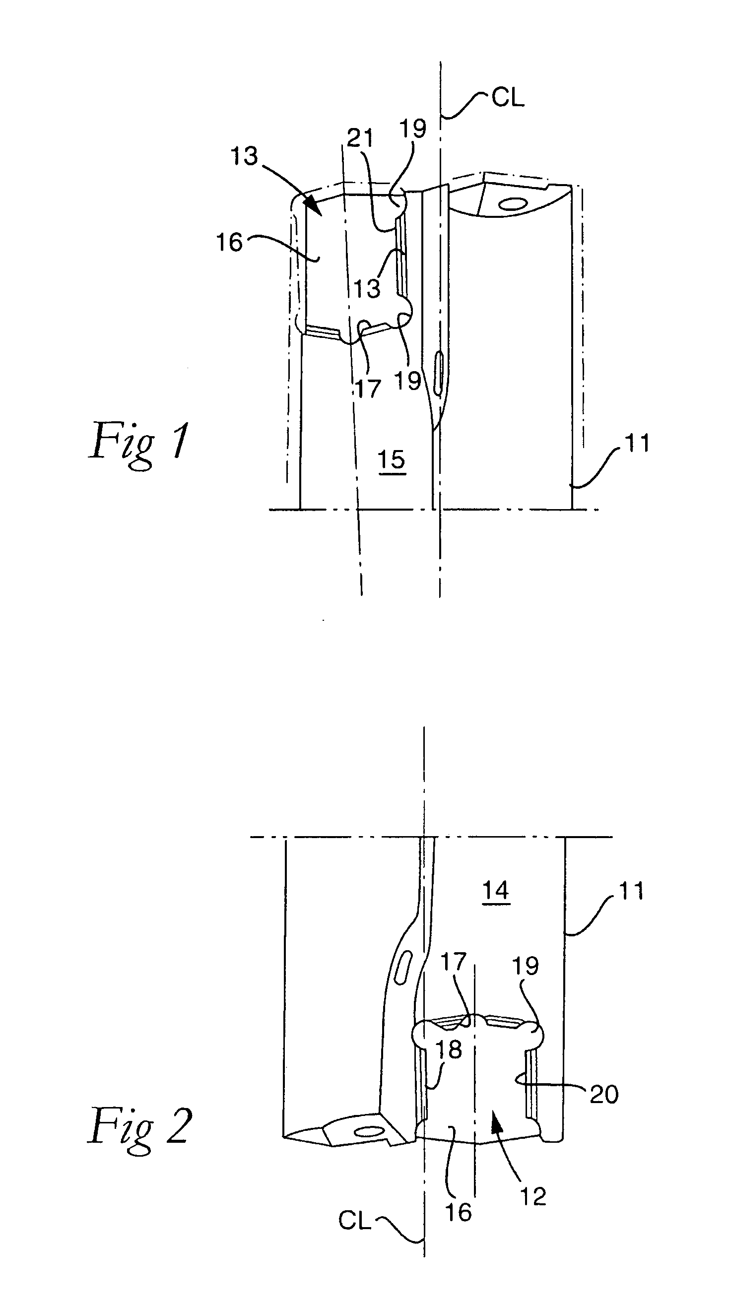
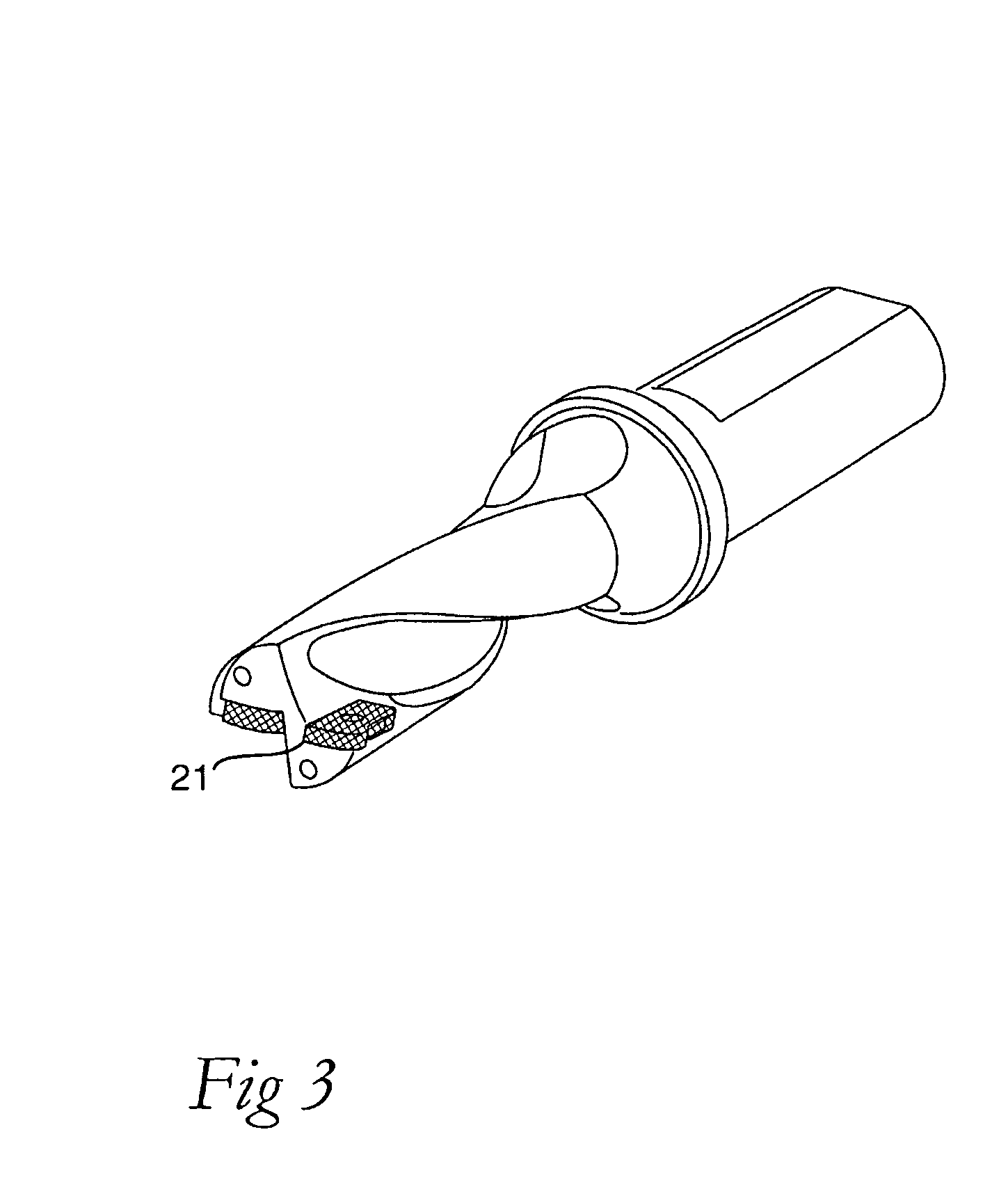
  • Holder for a cutting tool for metalworking and a method for the production of a holder for a cutting tool
  • Holder for a cutting tool for metalworking and a method for the production of a holder for a cutting tool
  • Holder for a cutting tool for metalworking and a method for the production of a holder for a cutting tool

Examples


example 1

[0034] Indexable short hole drill according to the invention, were prepared to final shape and dimension from tool steel SS2242. They were depth-hardened by heating to 960° C. followed by quenching in air to having a yield point in tension of 1520 N / mm2 and a hardness of 50 HRC. After that, the tools were shot peened over the entire holder body under the following conditions:

[0035] Angle of incidence: 90 deg relative the longitudinal axis of the drill

[0036] Distance between nozzle and tool holder: 100 mm

[0037] Speed of rotation, holder body: 30 rev / min

[0038] Time: 60 s

[0039] Media: 52 HRC, round steel spheres, 0.20 mm

[0040] Pressure and flow were adjusted to reach Almen-value of 18A.

example 2

[0041] Example 1 was repeated and additional to the hardening was nitrocarburising treatment undertaken as disclosed in of US 2005 / 0002744.

example 3

[0042] The tool holders from Examples 1 and 2 provided with cemented carbide cutting inserts were tested in short hole drilling operation 60 mm deep. Holes were drilled in material SS2541 300 HB with cutting data of speed of 200 m / min and feed of 0.20 mm / rev. These cutting data result in a force of 85% of the material yield tension. As a further reference a commercially available depth-hardened and cold blackened drill of the same type was tested. Tool life criterion was breakage of tool holder.

[0043] Result:


PUM

PropertyMeasurementUnit
Fractionaaaaaaaaaa
Structureaaaaaaaaaa
Fatigue strengthaaaaaaaaaa

Abstract

There is disclosed a holder for a cutting tool and a method for the production of a cutting tool for metalworking that results in a holder body having increased fatigue strength at loads over 60% of the yield point in tension. The method and the tool are characterized in that the holder body of the tool is subjected to a hardening process resulting in deep hardening, and that the holder body then is subjected to a surface treatment resulting in a strain hardening of the surface in order to introduce compressive stresses in the surface zone of the holder body.

Description

BACKGROUND OF THE INVENTION [0001] The present invention relates to a type of holder for a cutting tool for metalworking as well as a method for the production of a holder for a cutting tool, such as holder bodies having one or more insert seats for indexable inserts. As examples of such tools, drills may be mentioned having a plurality of cutting inserts of cemented carbide, cermets or ceramics. [0002] Cutting tools for chip-removing machining in, for instance, metallic materials, are available in many different types comprising tools for drilling, milling and turning. Common to these tools is that they usually comprise a holder body as well as one or more cutting inserts received in insert seats in the holder body intended therefore. Usually, the holder body is manufactured from hardened steel and subsequently cold blackened to obtain a black surface. The cutting inserts are made from cemented carbide, cermets or ceramics. [0003] The loads, static and dynamic, on tools for cutting...

Claims


Application Information

Patent Timeline
IPC IPC(8): B21K5/04
CPCB23B51/04B23P9/00C21D9/22C21D1/06C21D7/06B23P15/28B23B27/00B23B29/04B23B29/00B23B29/24B23C5/16
Inventor TUBINGER, KLASLUNDGREN, ROGERHOGLUND, DAN
Owner SANDVIK INTELLECTUAL PROPERTY AB
Learn More