Drill Bit and Cutting Inserts For Hard/Abrasive Formations

a hard/abrasive formation and drill bit technology, applied in the field of earth-moving drill bits, can solve the problems of increasing the difficulty of inserting drilling equipment into the borehole, increasing the cost of drilling equipment, so as to improve the rop, reduce the wear rate, and improve the durability

Active Publication Date: 2006-11-23
SMITH INT INC
View PDF99 Cites 35 Cited by
  • Summary
  • Abstract
  • Description
  • Claims
  • Application Information

AI Technical Summary

Benefits of technology

[0019] The inserts described herein are intended for hard and / or abrasive formations to provide enhanced ROP, durability and reduced wear rate relative to cutter elements having conventional shapes and geometries.

Problems solved by technology

As is thus obvious, this process, known as a “trip” of the drill string, requires considerable time, effort and expense.
If gage is not maintained at a relatively constant dimension, it becomes more difficult, and thus more costly, to insert drilling apparatus into the borehole than if the borehole had a constant diameter.
Thus, by the time it reaches the bottom, the bit may have experienced a substantial amount of wear that it would not have experienced had the prior bit been able to maintain full gage.
Such wear will shorten the life of the newly-inserted bit, thus prematurely requiring the time consuming and expensive process of removing the drill string, replacing the worn bit, and reinstalling another new bit downhole.
Excessive wear of the heel inserts leads to an undergage borehole, decreased ROP, increased loading on the other cutter elements on the bit, and may accelerate wear of the cutter bearing, and ultimately lead to bit failure.
However, in hard formations, such longer extensions make the inserts more susceptible to failure due to breakage.
Although such inserts with their shorter extensions have generally avoided breakage problems associated with longer and more aggressive inserts, and although the relativity sharp chisel and conical shapes provide reasonable rates of penetration and bit life they tend wear at a fast rate in hard abrasive formations because of the sharp tip geometry which reduces the footage drilled.

Method used


Image

  • Drill Bit and Cutting Inserts For Hard/Abrasive Formations
  • Drill Bit and Cutting Inserts For Hard/Abrasive Formations
  • Drill Bit and Cutting Inserts For Hard/Abrasive Formations

Examples


Embodiment Construction

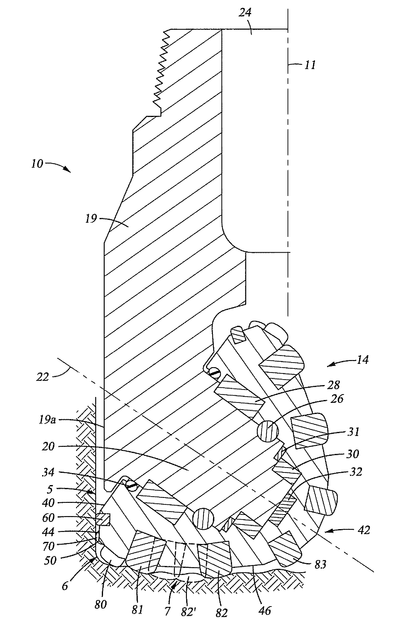
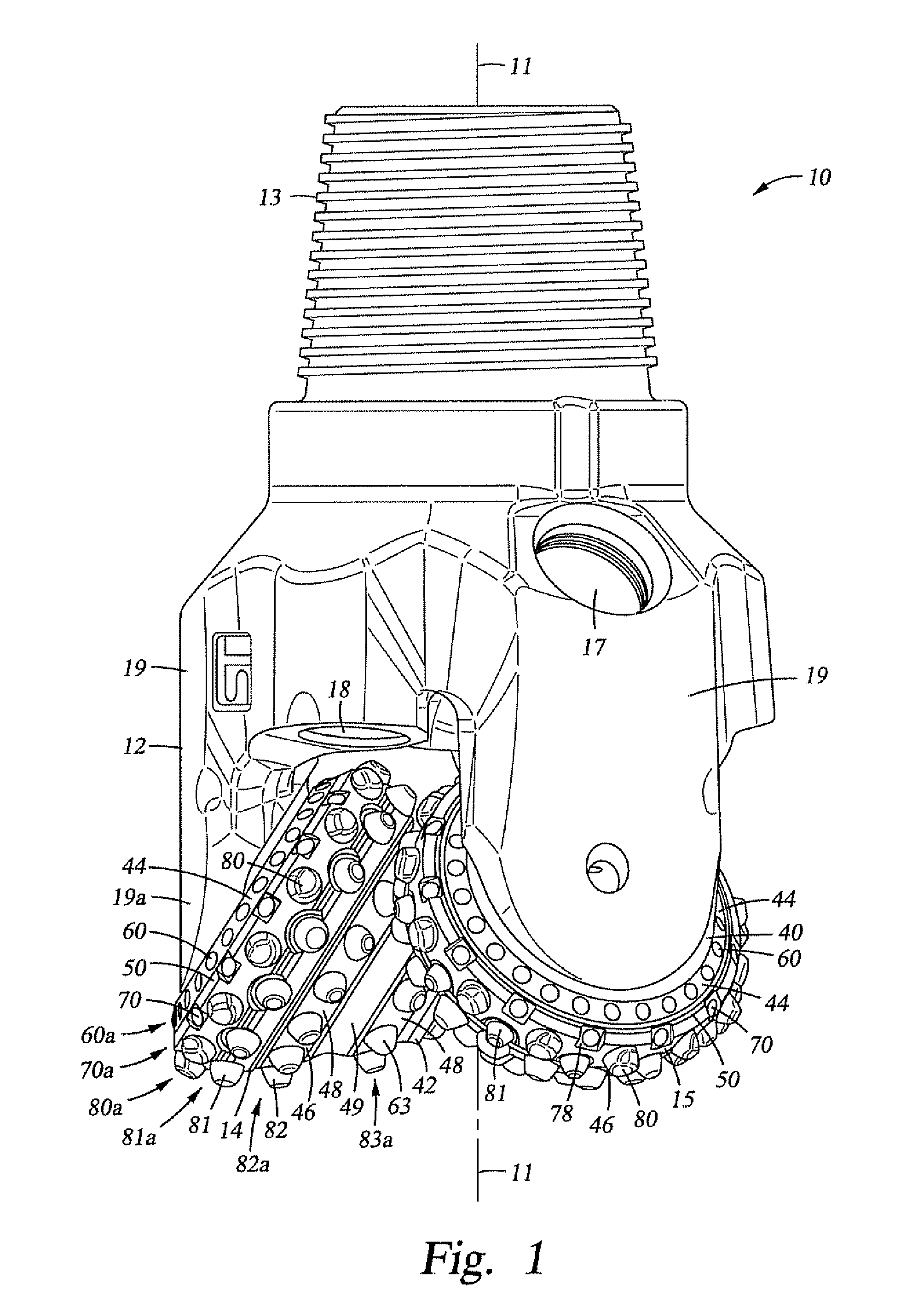
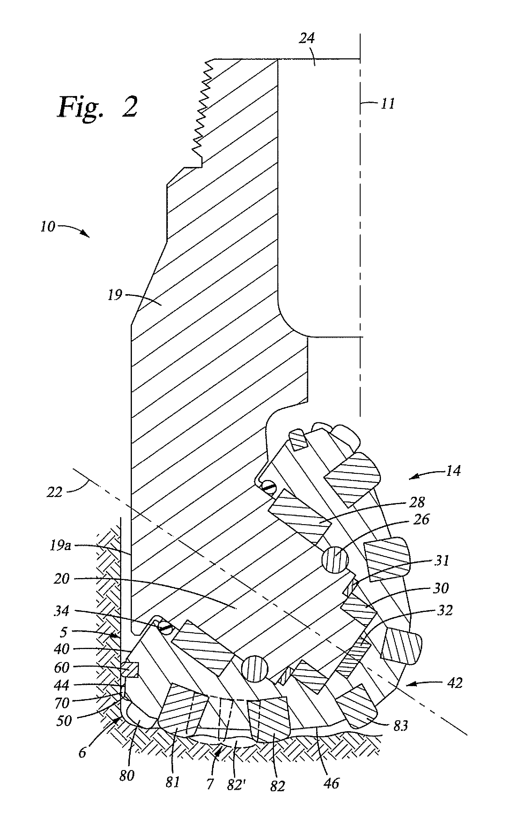
[0014] These and other needs in the art are addressed in one embodiment by a rolling cone drill bit for drilling a borehole in earthen formations. In an embodiment, the bit comprises a bit body having a bit axis. In addition, the bit comprises at least one rolling cone cutter mounted on the bit body for rotation about a cone axis and having a first surface for cutting the borehole bottom and second surface for cutting the borehole sidewall. Further, the bit comprises a plurality of cutter elements secured to the cone cutter and extending from the first surface and positioned in a first circumferential row, wherein at least one of the cutter elements comprises a cutter element axis, a base portion having a diameter, and a cutting portion extending from the base portion to a point furthermost from the base portion defining an extension height. Still further, the ratio of the cross-sectional area of the cutter element defined by a plane perpendicular to the cutter element axis at a poi...


PUM


Abstract

A rolling cone drill bit comprises a plurality of bottomhole cutter elements positioned in a first circumferential row, wherein at least one of the cutter elements comprises a cutting portion extending from a base portion to a point furthermost from the base portion, defining an extension height. The ratio of the cross-sectional area of the cutter element at a point equal to ninety-four percent of the extension height to the cross-sectional area of the cutter element base is greater than 0.2. Moreover, the ratio of the extension height to the base diameter is not greater than 0.75.

Description

CROSS-REFERENCE TO RELATED APPLICATIONS [0001] The present application claims the benefit of 35 U.S.C. 111(b) provisional application Ser. No. 60 / 681,692 filed May 17, 2005, and entitled Drill Bit and Cutting Inserts For Hard / Abrasive Formations.STATEMENT REGARDING FEDERALLY SPONSORED RESEARCH OR DEVELOPMENT [0002] Not Applicable. BACKGROUND OF THE INVENTION [0003] The invention relates generally to earth-boring bits used to drill a borehole for the ultimate recovery of oil, gas or minerals. More particularly, the invention relates to rolling cone rock bits and to an improved cutting structure for such bits. Still more particularly, the invention relates to enhancements in cutter element geometry, to increase bit durability and rate of penetration and enhance the bit's ability to maintain gage in hard and abrasive formations. [0004] An earth-boring drill bit is typically mounted on the lower end of a drill string and is rotated by rotating the drill string at the surface or by actua...

Claims


Application Information

Patent Timeline
Patent Type & Authority Applications(United States)
IPC IPC(8): E21B10/36
CPCE21B10/52E21B10/16
Inventor PORTWOOD, GARYWILSON, PETERTEDESCHI, LUCABAKER, BRYCEBRIETZKE, DANIEL W.
Owner SMITH INT INC
Why Eureka
Try Eureka