Electromagnetic driving wave soldering pot

a driving wave and soldering pot technology, applied in the direction of welding/cutting media/materials, manufacturing tools, solventing apparatus, etc., can solve the problems of increasing oxidation, forming lots of scruff, and inconvenient use for users, and achieves less oxide generation, stable wave, and less oxide generation.

Inactive Publication Date: 2006-11-23
SHENZHEN JT AUTOMATION EQUIP CO LTD
View PDF4 Cites 6 Cited by
  • Summary
  • Abstract
  • Description
  • Claims
  • Application Information

AI Technical Summary

Benefits of technology

[0016] In contrast with the conventional technology, the advantages of the present invention are in that the electromagnetic driving wave soldering pot according to the present invention uses a three-phase asynchronism induced electromagnetic pump to generate a straight thrust, such that the rotation of the blade of the mechanical pump is avoided, which thus ensures a stable wave, small vibration of the liquid surface in the tin bath, and less oxide generation. Because of the absence of the rotation component, there is no abrasion, which realizes free of maintenance, and eliminates the periodical maintenance. Therefore the cost is reduced and can facilitate the user. On the other hand, the electromagnetic driving wave soldering pot according to the present invention uses common three-phase alternating voltage, that is, the phase difference of the current is 120°. Therefore, there is no need for specific device to convert the voltage, i.e. the voltage can be used directly. Furthermore, the axes of the three coils of the electromagnetic pump spaced apart for ⅓ of the coil-side space of the one coil, and the current phase difference therebetween is 120°, therefore the composite vector of the positive (i.e. the direction along the flow of the liquid metal) magnetic field force the liquid metal to move toward the nozzle along the pump slot, while the composite vector of the negative (i.e. the opposite direction relative to the flow direction of the liquid metal) magnetic field is zero, this thus completely eliminates the power loss caused by the negative magnetic field, and the power of the alternating magnetic field can be effectively used. Because the energy consumption is decreased to 50% while the thrust and flow rate are increased by over 2 times, this electromagnetic driving wave soldering pot can totally replace the conventional mechanical pump and meet the requirement of the practical production.

Problems solved by technology

Thus not only the solder is subject to contaminating, but also the worn blade and other components are required to be maintained and replaced periodically, resulting in inconvenience to the user.
Additionally, the rotation movement of the mechanical pump causes disturbance of the surface of the tin solder, which increases the oxidation and forms lots of scruff.
Although both may overcome the abrasion problem of the mechanical pump, the former tends to generate oxidized residue and mask electrodes, which will cause the wave to be unstable and even significantly fluctuated, while the latter form a component of the forward magnetic field by a phase difference caused by a magnetic path difference of the electromagnet, therefore the component of the magnetic field is limited and efficiency is poor.
Such specific device is complicated in structure and very costly, thus it is difficult to decrease the cost of the wave soldering pot.
Therefore, the three-phase electromagnetic pump cannot completely eliminate the power loss caused by the reverse magnetic field, the energy of the three-phase alternating magnetic field cannot be effectively used, and the thrust and the flow rate thereof are limited.
Therefore such a three-phase electromagnetic pump cannot fully replace the conventional mechanical pump in practical application, and cannot meet the requirement of real production as well.

Method used


Image

  • Electromagnetic driving wave soldering pot
  • Electromagnetic driving wave soldering pot
  • Electromagnetic driving wave soldering pot

Examples


Embodiment Construction

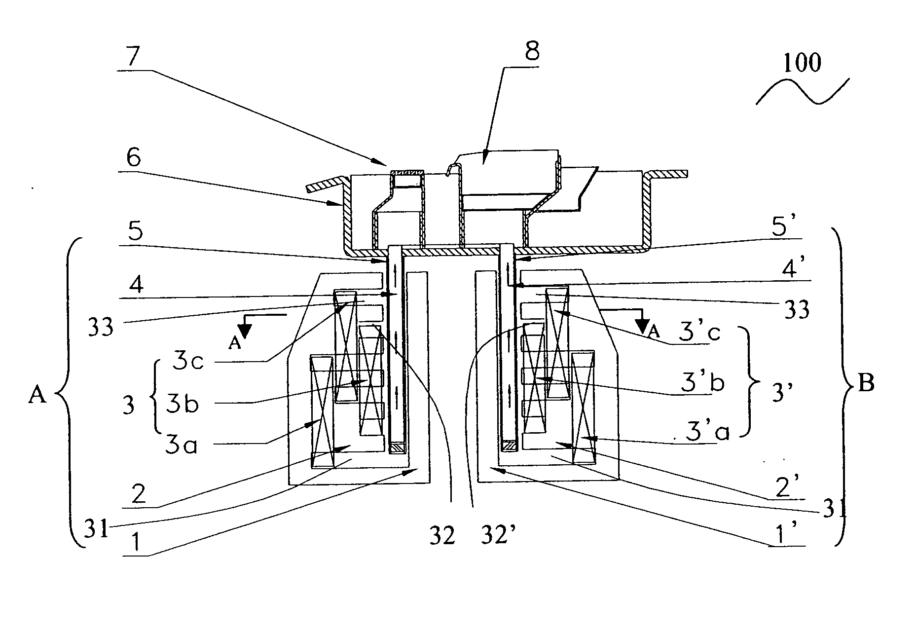
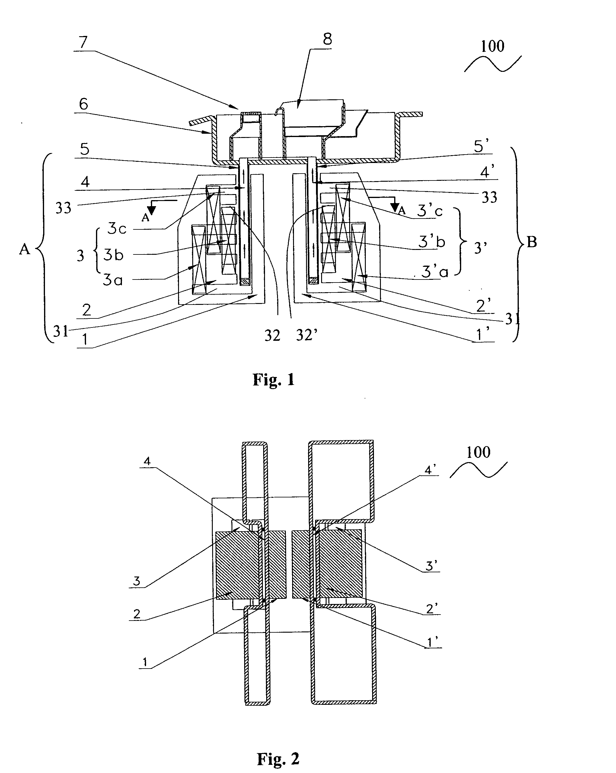
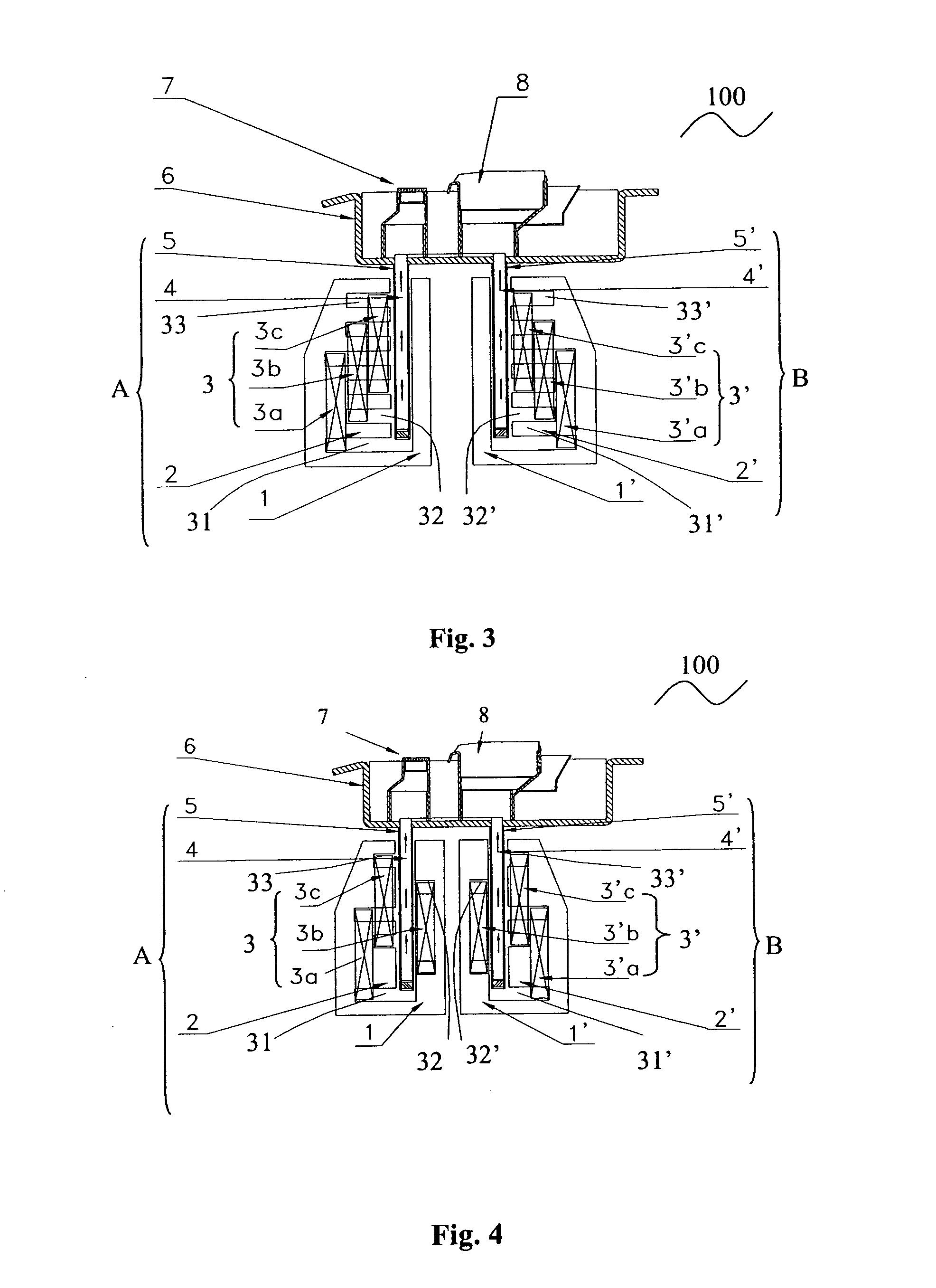
[0022] As shown in FIGS. 1 and 2, the electromagnetic driving wave soldering pot 100 according to the present invention includes a first electromagnetic pump A, a second electromagnetic pump B, a tin bath 6 and nozzles 7, 8. The first electromagnetic pump A includes iron cores 1, 2, an excitation coils group 3, and a pump slot 5. The second electromagnetic pump B includes iron cores 1′, 2′, an excitation coil group 3′ and a pump slot 5′. Since the iron cores 1, 2 and the excitation coil group 3 of the first electromagnetic pump A are substantially identical with that of the second electromagnetic pump B, the detailed description hereinafter is directed solely to the first electromagnetic pump A.

[0023] The iron cores 1, 2 may be designed as an integral, or may be separately provided. If the iron cores 1, 2 are separately provided, then the iron cores 1, 2 must reliably contact to each other to ensure the electrical and magnetical communication between the iron cores 1, 2. A pluralit...


PUM


Abstract

The present invention discloses an electromagnetic driving wave soldering pot, includes an electromagnetic pump, a tin bath and a nozzle, and the electromagnetic pump includes an iron core, a coil group provided in the two iron core and a pump slot, the pump slot communicates with the nozzle, and the coils group includes three coils, which are supplied with three-phase alternating current excitation power supply having a phase difference of 120°. Because of the absence of any moving components and thus abrasion, the present invention not only overcomes the defects of being abrased badly and eroded easily, as well as solder being oxidized seriously in the conventional wave soldering pot, but also completely eliminates the power loss caused by the negative magnetic field in the alternating magnetic field, and effectively uses the power of the alternating magnetic field. Furthermore, because the energy consumption is decreased to 50% while the thrust and flow rate are Is increased over 2 times, this electromagnetic driving wave soldering pot can totally replace the conventional mechanical pump and meet the requirement of the practical production.

Description

TECHNICAL FIELD [0001] The present invention relates to a soldering device using liquid metal solder which is employed in producing electronic products, and particularly to an electromagnetic driving wave soldering pot and a wave driving electromagnetic pump used in the soldering pot for driving liquid metal solder. BACKGROUND OF THE INVENTION [0002] In the Surface Mounting Technology (SMT), especially in the soldering technologies of dual wave soldering for printed boards and single wave soldering for Surface Mounting Components (SMC), both the wave soldering technology and the wave soldering pot which use liquid solder must be employed. [0003] Generally, most of the wave soldering machines are of mechanical pump type. Due to rotating at high temperature (about 250° C.), the blade of the mechanical pump is abraded quickly. Thus not only the solder is subject to contaminating, but also the worn blade and other components are required to be maintained and replaced periodically, resul...

Claims


Application Information

Patent Timeline
Patent Type & Authority Applications(United States)
IPC IPC(8): B23K35/14
CPCB23K3/0653H02K44/06B23K35/02
Inventor CHAI, MINGHUA
Owner SHENZHEN JT AUTOMATION EQUIP CO LTD
Why Eureka
Try Eureka