Bone treatment systems and methods

a bone treatment and bone technology, applied in the field of medical devices, can solve the problems of fractures in the spine and hips, affecting mobility and quality of life, and the medical advances aimed at slowing or arresting bone loss from aging have not provided solutions to this problem, so as to achieve a greater degree of control over the introduction of bone support materials and improve outcomes

Active Publication Date: 2006-11-23
DFINE INC
View PDF99 Cites 73 Cited by
  • Summary
  • Abstract
  • Description
  • Claims
  • Application Information

AI Technical Summary

Benefits of technology

[0023] There is a general need to provide systems and methods for use in treatment of vertebral compression fractures that provide a greater degree of control over introduction of bone support material, and that provide better outcomes. The present invention meets this need and provides several other advantages in a novel and nonobvious manner.

Problems solved by technology

Medical advances aimed at slowing or arresting bone loss from aging have not provided solutions to this problem.
Osteoporosis affects the entire skeleton but most commonly causes fractures in the spine and hip.
Spinal or vertebral fractures also have serious consequences, with patients suffering from loss of height, deformity and persistent pain which can significantly impair mobility and quality of life.
Osteoporosis describes a condition of decreased bone mass that leads to fragile bones which are at an increased risk for fractures.
In an osteoporotic bone, the sponge-like cancellous bone has pores or voids that increase in dimension, making the bone very fragile.
In an elderly patient, bone resorption can surpass bone formation thus resulting in deterioration of bone density.
The bilateral transpedicular approach is typically used because inadequate PMMA infill is achieved with a unilateral approach.
Since the PMMA needs to be forced into cancellous bone, the technique requires high pressures and fairly low viscosity cement.
Since the cortical bone of the targeted vertebra may have a recent fracture, there is the potential of PMMA leakage.
Leakage of PMMA during vertebroplasty can result in very serious complications including compression of adjacent structures that necessitate emergency decompressive surgery.
The exothermic reaction of PMMA carries potential catastrophic consequences if thermal damage were to extend to the dural sac, cord, and nerve roots.
Vertebroplasty patients often return with new pain caused by a new vertebral body fracture.
Leakage of cement into an adjacent disc space during vertebroplasty increases the risk of a new fracture of adjacent vertebral bodies.
Another life-threatening complication of vertebroplasty is pulmonary embolism.
The vapors from PMMA preparation and injection are also cause for concern.
Another disadvantage of PMMA is its inability to undergo remodeling—and the inability to use the PMMA to deliver osteoinductive agents, growth factors, chemotherapeutic agents and the like.
Yet another disadvantage of PMMA is the need to add radiopaque agents which lower its viscosity with unclear consequences on its long-term endurance.
In both higher pressure cement injection (vertebroplasty) and balloon-tamped cementing procedures (kyphoplasty), the methods do not provide for well controlled augmentation of vertebral body height.
Thus, the reduction of a vertebral compression fracture is not optimized or controlled in high pressure balloons as forces of balloon expansion occur in multiple directions.
Expansion of the balloon under high pressures close to cortical bone can fracture the cortical bone, or cause regional damage to the cortical bone that can result in cortical bone necrosis.
Such cortical bone damage is highly undesirable and results in weakened cortical endplates.
Kyphoplasty also does not provide a distraction mechanism capable of 100% vertebral height restoration.
Further, the kyphoplasty balloons under very high pressure typically apply forces to vertebral endplates within a central region of the cortical bone that may be weak, rather than distributing forces over the endplate.

Method used


Image

  • Bone treatment systems and methods
  • Bone treatment systems and methods
  • Bone treatment systems and methods

Examples


Embodiment Construction

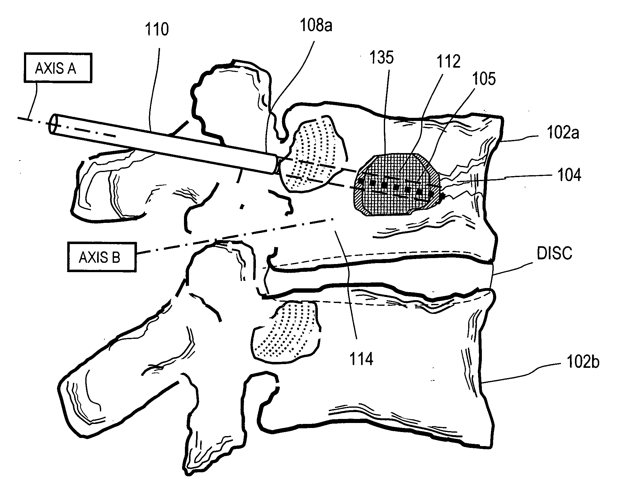
[0031] In FIG. 1, it can be seen that vertebral body 102b has a wedge vertebral compression fracture (VCF) indicated at 104 and the methods of the invention are directed to safely introducing a bone cement into cancellous bone to eliminate pain and to reduce the fracture. Vertebral body 102a is susceptible to a VCF following treatment of the fractured vertebra 102b since biomechanical loading will be altered. The present invention includes systems for prophylactically treating a vertebra that is adjacent to vertebral compression fracture, as well as for the treating the fractured vertebra.

[0032]FIG. 1 illustrates an initial step of a method of the invention wherein the distal working end 105 of an elongate introducer 110 is introduced through the saddle of pedicle 108a for penetration along axis A into the osteoporotic cancellous bone 112. It should be appreciated that the instrument also can be introduced into the vertebra in an extrapedicular approach, for example, through the co...


PUM


Abstract

Methods and instruments for treating an osteoporotic vertebral body or for treating a vertebral compression fracture. An exemplary method includes introducing an open knit structure together with a bone cement into a bone wherein the knit structure extends substantially throughout the interior of the cement volume. In one aspect of the invention, the bone cement volumes cures with the filament structure reinforcing the cement. In another aspect of the invention, the open knit structure is configured to direct flows of bone cement to apply forces for reducing a vertebral compression fracture. In another aspect of the invention, the system provides bone cement flows that extend through the knit structure thus allowing the cement to fully interdigitate with the cancellous bone.

Description

CROSS-REFERENCE TO RELATED APPLICATIONS [0001] This application claims benefit of Provisional U.S. Patent Application Ser. No. 60 / 625,347 filed Nov. 5, 2004 titled Systems and Methods for Treating Vertebral Fractures and also claims benefit of Provisional U.S. Patent Application Ser. No. 60 / 626,701 filed Nov. 10, 2004 titled Systems and Methods for Treating Vertebral Fractures. This application also is related to U.S. application Ser. No. 11 / 165,652 (Atty. Docket No. DFINE.001A1), filed Jun. 24, 2005 titled Bone Treatment Systems and Methods; and U.S. patent application Ser. No. 11 / 165,651 (Atty. Docket No. DFINE.001A2), filed Jun. 24, 2005, titled Bone Treatment Systems and Methods. The entire contents of all of the above cross-referenced applications are hereby incorporated by reference in their entirety and should be considered a part of this specification.BACKGROUND OF THE INVENTION [0002] 1. Field of the Invention [0003] The present invention relates to medical devices, and mor...

Claims


Application Information

Patent Timeline
Patent Type & Authority Applications(United States)
IPC IPC(8): A61F2/00
CPCA61B17/7098
Inventor SHADDUCK, JOHN H.TRUCKAI, CSABA
Owner DFINE INC
Why Eureka
Try Eureka