Composite steel-wood floor structure

a floor structure and composite technology, applied in the direction of building components, constructions, building constructions, etc., can solve the problems of general incompatibility between the cement surface and the floor covering, the lack of workability, and the difficulty of use, so as to increase the strength performance of the floor structure, and increase the effect of the floor structur

Inactive Publication Date: 2006-11-30
HUBER ENGINEERED WOODS
View PDF50 Cites 9 Cited by
  • Summary
  • Abstract
  • Description
  • Claims
  • Application Information

AI Technical Summary

Benefits of technology

[0019] A particular advantage of the present invention is that the disclosed floor structure allows for the disentanglement of the building services, which have relatively shorts life spans (e.g., 10 years) from the floor and building itself, which should have a much longer life span (e.g., over 100 years). Utilizing the presently disclosed floor structure allows for the building services to be easily upgraded in the future when necessary or when more sophisticated equipment becomes available.
[0020] Yet another advantage of this arrangement as found in the present invention is that it also increases the strength performance of the floor structure because the larger footprint of the channel on the lower wood composite board 5 acts to reinforce the floor structure in the area where the high tension forces make the floor structure more likely to fail (i.e., the lower wood panels that form the lower surface of the floor structure) than at other areas of the floor structure.
[0021] As mentioned above, the channels 17 must be securely attached to the upper and lower wood 5, 8 composite boards, with nails, screws, adhesive glue, or other permanent fasteners as described above. The channels 17 may additionally have extending tabs 23 (See FIG. 2a) to facilitate attachment of the channels to the upper surface 5. Fasteners may be selected from readily available nails and fasteners such as the Primeguard Plus™ exterior screws available from PrimeSource Building Products, Inc., Carrollton, Tex.
[0022] In addition, an adhesive may also be used to ensure that the channels are sufficiently fastened to the upper and lower composite boards so that the channels can bring strength reinforcing properties as described above. This adhesive is typically applied in beads of a typical width of ¼ inch, but wider or thinner depending on the specific individual needs. The adhesive resin used to from the bead in the present invention may be selected from a variety of different polymer materials such as epoxies, phenolic, resorcinol, acrylic, polyurethane, phenolic-resorcinol-formaldehyde resin, and polymeric methylenediisocyanate (“pMDI”). The selection will largely depend on the cost and performance targets specified. Some examples of specific resin systems that are suitable for use in the present invention include ISOSET® UX-100 Adhesive, available from Ashland Specialty Chemical Company, Columbus, Ohio. ISOSET is a two-part resin system, based on a 100-percent solids polyurethane adhesive, blended with conventional ISOSET adhesive. This system offers faster strength and faster complete cure times, while providing excellent strength performance. Particularly preferred is PL® Premium subfloor adhesive available from PL Sealants and Adhesives, Mentor, Ohio.
[0023] Additional options or features can be added to the wood board as well. For example, tongue and groove surfaces (not illustrated in figures) can be added to the edges of the floor structure to ensure good, tight fits with adjacent floor structure pieces. Similarly, interlocking cams (not illustrated in figures) can be formed on the longitudinal edges to pull the panels tight during assembly. Also four machined holes (not illustrated in present FIG. 1), two holes at each panel end, may be added to the lower panel as a means of easily attaching cables for lifting and lowering the panel into place with a crane.
[0024] When the floor structures are fully assembled so that the webstocks are disposed between the upper and lower levels (thereby interconnecting the panels) and the channels are disposed in the space between the upper and lower levels, then the overall thickness of the floor structure will be about 8 inches to about 24 inches, preferably about 10 inches to about 14 inches.

Problems solved by technology

Yet another important factor that has been insufficiently addressed in past floor structures is that the floor structure should be compatible with potential floor coverings to be used over it.
While this floor is capable of being pre-assembled it has a number of drawbacks, notably a lack of workability, difficulty of use and a general incompatibility between its cement surface and floor coverings to be installed on this surface.
However, these panels are not really applicable for forming floors, they are actually meant to form wall panels and in most cases would be inapplicable for forming floor structures.

Method used


Image

  • Composite steel-wood floor structure
  • Composite steel-wood floor structure

Examples


example 1

Present Invention

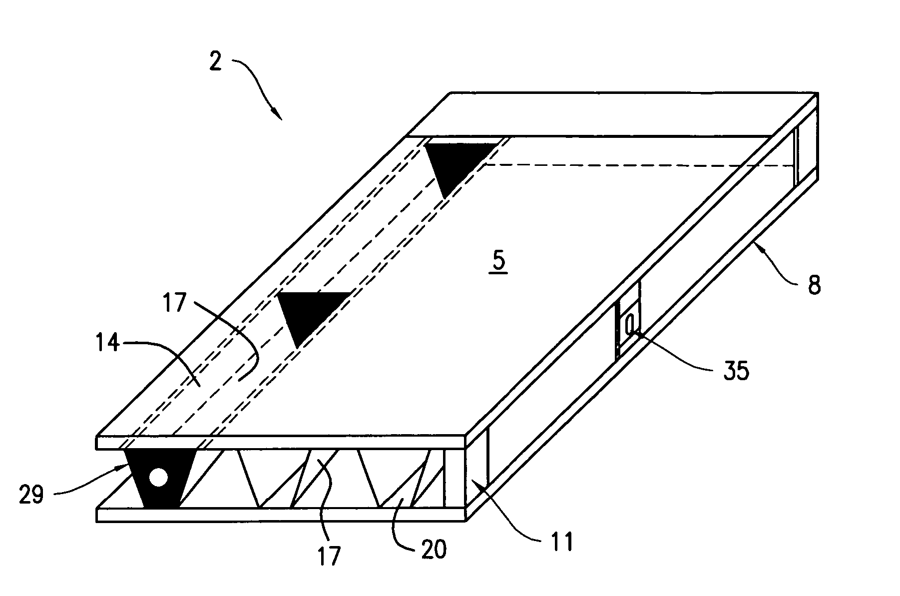
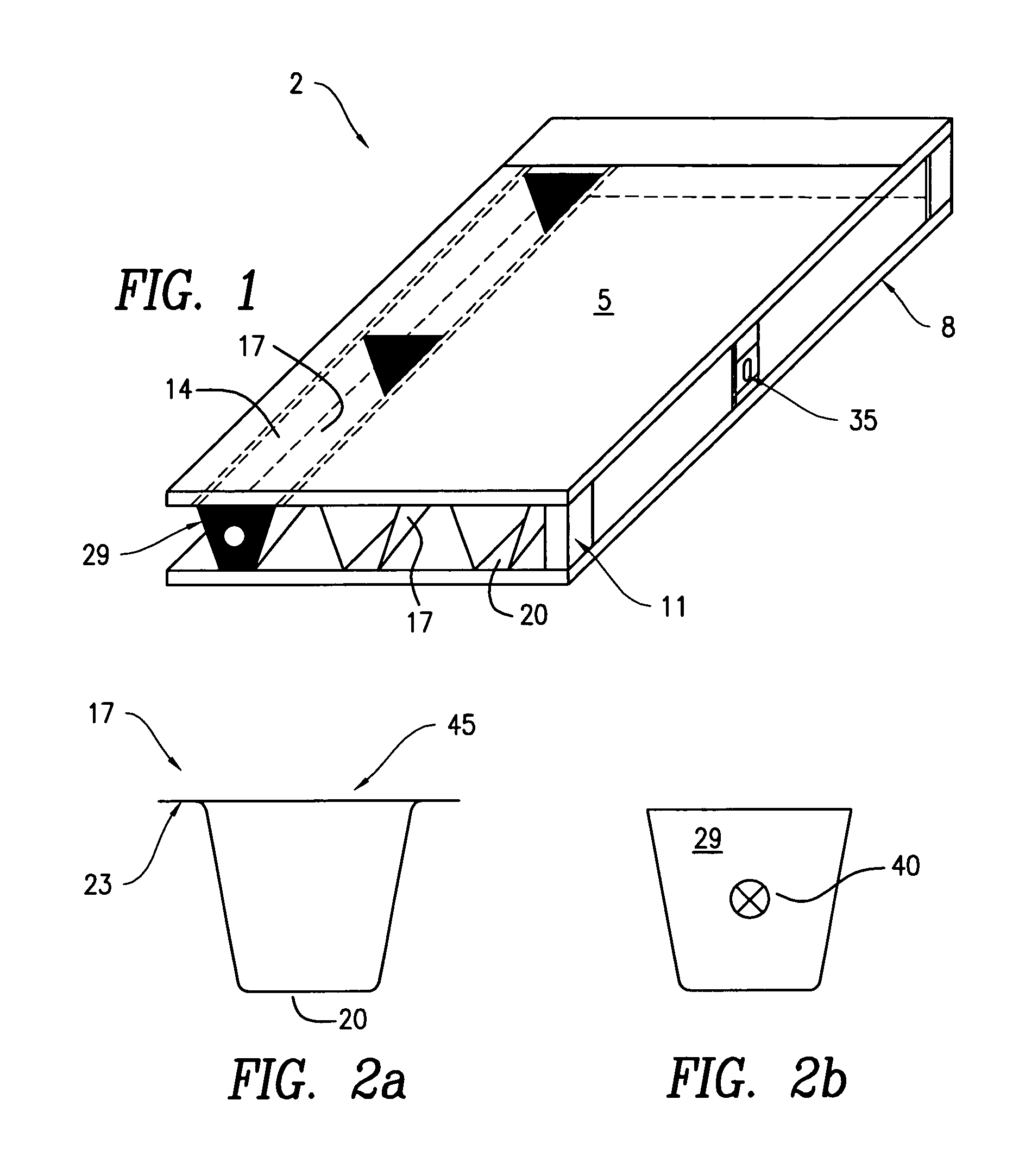
[0026] Floor structures were prepared according to the present invention as follows. The floor structures were four feet wide, 20 foot long, and 9.5 inches thick. The upper and lower composite wood boards were 23 / 32″ AdvanTech boards. Between the upper and lower composite wood boards were arranged three channels, cross sectional illustrations and dimensions of these channels are shown in FIG. 2. The channels themselves were 20 feet long, and stiffeners at each end and along the channels at a longitudinal spacing of one stiffener for every four feet.

[0027] Screws were inserted every 8-inches as indicated by in FIG. 2 to fasten the metals channels to the upper and lower composite wood boards. The screws used were Primeguard Plus™ exterior screws. As can be seen the metal channel in FIG. 2b is in the shape of an isosceles trapezoid, with the top of the channel 14 having a length of seven inches, the height of the trapezoidal channel 14 being 8 inches, the non-paralle...

example 2

Prior Art

[0030] A conventional floor structure was built with concrete foundation walls made according to size and set at the proper spacing. The 2×4 plate was bolted down to the top of the concrete supports, and the rimboard was placed on the plate and attached thereto with nail fasteners, at an industry-wide standard spacing for nails of every 12″, I Joists were installed on the rimboard and AdvanTech floor sheathing was fastened to the I Joists with a continuous bead of polyurethane construction adhesive. The I joists were made from ⅜ inch OSB webstock and solid wood lumber flanges that were 1.5 inch by 2.5 inch.

[0031] Examples 1 and 2 were then tested to measure the stiffness of the flooring structures and assess whether they are sufficiently stiff as to avoid undesirable vibrations. A drop weight apparatus was used to apply a repeatable dynamic loading to the floor systems. Two accelerometers and two linear variable displacement transducers (LVDTs) were installed at the cente...


PUM


Abstract

Disclosed is a floor structure comprising: an upper surface arranged in parallel to a lower surface; and one or more channels disposed vertically between upper and lower surfaces and longitudinally extending along the upper and lower surfaces, each of the one or more channels having a top and a bottom.

Description

BACKGROUND OF THE INVENTION [0001] A structural, weight-bearing floor system is constructed by laying a floor deck across a number of underlying, supporting joists or beam members. The deck may be made of a variety of different materials, however generally the deck will be constructed of wood, such as wood panels set to lie across foundation walls or beam members, so as to replace the use of subfloor panels set upon underlying wood joists. [0002] In designing a floor structure system, a number of factors are important, notably that the combination of the wood panels and underlying joists create a strong, stiff floor. The floor should also have other important features, for example, it should be relatively easy to install as well as be capable of accommodating building services such as HVAC, plumbing, as well as fiber optics and other communication cables. Yet another important factor that has been insufficiently addressed in past floor structures is that the floor structure should b...

Claims


Application Information

Patent Timeline
Patent Type & Authority Applications(United States)
IPC IPC(8): E04C2/34
CPCE04C2/34E04B5/10
Inventor BARKER, JOELTHOMAS, VINCENT B.FRIDLEY, KENNETHRANDALL, ROBERTJOHNSON, WILLIAM STEVEN
Owner HUBER ENGINEERED WOODS
Why Eureka
Try Eureka